
CHAPTER I: CAPITAL DEVELOPMENT BOARD
SUBCHAPTER b: ACCESSIBILITY STANDARDS
PART 400 ILLINOIS ACCESSIBILITY CODE
SECTION 400.APPENDIX A ILLINOIS ACCESSIBILITY CODE
Section 400.APPENDIX A Illinois Accessibility Code
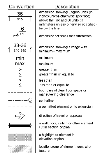
BOARD NOTE: In this Appendix A, italicization of text indicates that the Capital Development Board has adopted rules applicable in the State of Illinois that differ to some extent from the 2010 ADA Standards for Accessible Design. Defined terms are indicated by bold text.
CHAPTER 1: APPLICATION AND ADMINISTRATION
101.1 General. This document contains scoping and technical requirements for accessibility to sites, facilities, buildings, and elements by individuals with disabilities.
101.2 Buildings and Facilities Covered. This Code applies to all public facilities and multi-story housing as defined and governed by the Environmental Barriers Act and located, in whole or in part, within the legal geographic boundaries of the State of Illinois, unless specifically exempted in this Code.
101.3 Applicability, General. This Code is applicable when work involving new construction, alterations, additions, historic preservation, restoration, or reconstruction in whole or in part begins after the effective date of this Code. The Code becomes enforceable with the signing of a construction contract, issuance of an official authorization or permit for construction, or the start of construction, whichever occurs first.
101.4 Applicability to Federally Financed Facilities. The fact that a building or facility governed by the Environmental Barriers Act is also a facility financed by federal funds is no bar to the application of this Code.
101.5 Force of Law. This Code, together with the Environmental Barriers Act and the standards incorporated by reference identified in Section 105, has the force of a building code and as such is law in the State of Illinois.
101.6 Enforcement. The Attorney General shall have the authority to enforce this Code in accordance with Section 6 of the Environmental Barriers Act. The Attorney General may investigate any complaint or reported violation of the Environmental Barriers Act and, where necessary to ensure compliance, may do any of the following:
1. Conduct an investigation to determine if a violation of the Environmental Barriers Act and this Code exists. This includes the power to:
a. Require an individual or entity to file a statement or report in writing under oath or otherwise, as to all information the Attorney General may consider;
b. Examine under oath any person alleged to have participated in or with knowledge of the violations; and
c. Issue subpoenas or conduct hearings in aid of any investigation.
2. Bring an action for injunction to halt construction or alteration of any public facility or multi-story housing or to require compliance with this Code by any public facility or multi-story housing which has been or is being constructed or altered in violation of the Environmental Barriers Act and this Code.
3. Bring an action for mandamus.
4. Bring an action for penalties as follows:
a. Any owner of a public facility or multi-story housing in violation of the Environmental Barriers Act shall be subject to civil penalties in a sum not to exceed $250 per day, and each day the owner is in violation of the Environmental Barriers Act constitutes a separate offense;
b. Any architect or engineer negligently or intentionally stating pursuant to Section 5 of the Environmental Barriers Act that a plan is in compliance with the Environmental Barriers Act when such plan is not in compliance shall be subject to a suspension, revocation, or refusal of restoration of his or her certificate of registration or license pursuant to the Illinois Architecture Practice Act of 1989, the Professional Engineering Practice Act of 1989, and the Structural Engineering Practice Act of 1989; and
c. Any person who knowingly issues a building permit or other official authorization for the construction or alteration of a public facility or the construction of multi-story housing in violation of the Environmental Barriers Act shall be subject to civil penalties in a sum not to exceed $1,000.
5. Bring an action for any other appropriate relief, including, but not limited to, in lieu of a civil action, the entry of an Assurance of Voluntary Compliance with the individual or entity deemed to have violated the Environmental Barriers Act.
101.6.1 Continuity of Violation. A public facility or multi-story housing continues to be in violation of the Environmental Barriers Act and this Code following construction or alteration so long as the public facility or multi-story housing is not compliant with the Environmental Barriers Act and this Code.
101.7. Local Standards. The provisions of the Environmental Barriers Act and this Code constitute minimum requirements for all governmental units, including home rule units. Pursuant to Section of the, Environmental Barriers Act, any governmental unit may enact more stringent requirements to increase and facilitate access to the built environment by individuals with disabilities.
101.8 Revisions to Code. This Code may be revised from time to time by the Capital Development Board in accordance with the Illinois Administrative Procedure Act [5 ILCS 100] and Section 4 of the Environmental Barriers Act.
101.9 Permits/Statement of Compliance. Where permits are required for the construction or alteration of any public facility or multi-story housing unit, the plans and specifications submitted by the owner to obtain such a permit shall be examined for compliance with this Code by the administrative authority which issues the permit for construction.
101.9.1 Filing. Section 5(d) of the Environmental Barriers Act requires a Statement of Compliance by the architect/engineer unless the cost of construction or alteration is less than $50,000. For privately owned work it shall be filed with the local administrative authority or, in the absence of an administrative authority, with the County Clerk. For publicly-owned work, it shall be filed with the governmental unit contracting for the work.
101.9.2 Content and Signature. The Statement of Compliance shall be worded as follows and signed by the architect/engineer:
STATEMENT OF COMPLIANCE
I have prepared, or caused to be prepared under my direct supervision, the attached plans and specifications and state that, to the best of my knowledge and belief and to the extent of my contractual obligation, they are in compliance with the Environmental Barriers Act [410 ILCS 25] and the Illinois Accessibility Code (71 Ill. Adm. Code 400).
Signed: (Architect/Engineer)
SEAL ILLINOIS REGISTRATION NO:
Date:
101.9.3 Alternative to Statement of Compliance. The seal of the architect/engineer as required by Section 14 of the Illinois Architecture Practice Act of 1989, Section 12 of the Illinois Structural Engineering Licensing Act and Section 14 of the Illinois Professional Engineering Practice Act may be provided in lieu of the "Statement of Compliance" required in Section 101.9.2.
101.10 Effect on Removal of Barriers in Existing Facilities. This document does not address barrier removal in existing facilities. Buildings constructed prior to May 1, 1988 were not subject to the Illinois Accessibility Code. For guidance on removal of barriers in existing facilities, see Section 101.2 of the 2010 ADA Standards.
101.11 Waiver Prohibited. The requirements of this Code cannot be waived by any party.
102 Dimensions for Adults and Children
The technical requirements are based on adult dimensions and anthropometrics. In addition, this document includes technical requirements based on children's dimensions and anthropometrics for drinking fountains, water closets, toilet compartments, lavatories and sinks, dining surfaces, and work surfaces.
Nothing in these requirements prevents the use of designs, products, or technologies as alternatives to those prescribed, provided they result in substantially equivalent or greater accessibility and usability.
104.1 Dimensions. Dimensions that are not stated as "maximum" or "minimum" are absolute.
104.1.1 Construction and Manufacturing Tolerances. All dimensions are subject to conventional industry tolerances except where the requirement is stated as a range with specific minimum and maximum end points.
104.2 Calculation of Percentages. Where the required number of elements or facilities to be provided is determined by calculations of ratios or percentages and remainders or fractions result, the next greater whole number of such elements or facilities shall be provided. Where the determination of the required size or dimension of an element or facility involves ratios or percentages, rounding down for values less than one half shall be permitted.
104.3 Figures. Unless specifically stated otherwise, figures are provided for informational purposes only.
|
|
|
Figure 104 |
104.4 Mandatory Terms. Use of the terms "provide" or "shall" means the provision is mandatory.
105.1 General. The standards listed in 105.2 are incorporated by reference in this document and are part of the requirements to the prescribed extent of each such reference.
105.2 Referenced Standards. The specific edition of the standards listed below are referenced in this document. Where differences occur between this document and the referenced standards, this document applies.
105.2.1 ANSI/BHMA. Copies of the referenced standards may be obtained from the Builders Hardware Manufacturers Association, 355 Lexington Avenue, 17th floor, New York, NY 10017 (www.buildershardware.com).
ANSI/BHMA A156.10-1999 American National Standard for Power Operated Pedestrian Doors (see 404.3).
ANSI/BHMA A156.19-2002 American National Standard for Power Assist and Low Energy Power Operated Doors (see 404.3, 408.3.2.1, and 409.3.1).
105.2.2 ASME. Copies of the referenced standards may be obtained from the American Society of Mechanical Engineers, Three Park Avenue, New York, New York 10016 (www.asme.org).
ASME A17.1- 2013 Safety Code for Elevators and Escalators (see 407.1, 408.1, 409.1, and 810.9).
ASME A18.1-2011 Safety Standard for Platform Lifts and Stairway Chairlifts (see 410.1).
105.2.3 ASTM. Copies of the referenced standards may be obtained from the American Society for Testing and Materials, 100 Bar Harbor Drive, West Conshohocken, Pennsylvania 19428 (www.astm.org).
ASTM F 1292-13 Standard Specification for Impact Attenuation of Surfacing Materials within the Use Zone of Playground Equipment (see 1008.2.6.2).
ASTM F 1487-11 Standard Consumer Safety Performance Specification for Playground Equipment for Public Use (see 106.5).
ASTM F 1951-09b Standard Specification for Determination of Accessibility of Surface Systems under and around Playground Equipment (see 1008.2.6.1).
105.2.4 ICC/IBC. Copies of the referenced standard may be obtained from the International Code Council, 4051 Flossmoor Road, Country Club Hills, IL 60478 (www.iccsafe.org).
International Building Code, 2015 Edition (see 1005.2.1).
International Building Code, 2006 Edition, or later edition (see Definition of "Applicable Building Code").
105.2.5 NFPA. Copies of the referenced standards may be obtained from the National Fire Protection Association, 1 Batterymarch Park, Quincy, Massachusetts 02169-7471, (www.nfpa.org).
NFPA 72 National Fire Alarm Code, 2013 Edition (see 702.1 and 809.5.2).
105.2.6 National Park Service, U.S. Department of the Interior. Copies of the referenced standards may be obtained from the www.nps.gov/tps/standards/rehabilitation.htm or at your local library. It is also available from the Illinois State Historic Preservation Office. The Standards and Guidelines do not include any later amendments or editions.
"Secretary of the Interior's Standards for Rehabilitation and Guidelines for Rehabilitating Historic Buildings" (Revised 1992).
106.1 General. For the purpose of this document, the terms defined in 106.5 have the indicated meaning.
106.2 Terms Defined in Referenced Standards. Terms not defined in 106.5 but specifically defined in a referenced standard, shall have the specified meaning from the referenced standard unless otherwise stated.
106.3 Undefined Terms. The meaning of terms not specifically defined in 106.5 or in referenced standards shall be as defined by collegiate dictionaries in the sense that the context implies.
106.4 Interchangeability. Words, terms, and phrases used in the singular include the plural and those used in the plural include the singular.
106.5 Defined Terms.
Accessibility Code. As required by the Environmental Barriers Act, accessibility code means this Code.
Accessible. A site, building, facility, or portion thereof that complies with this Code.
Accessible Route. A continuous unobstructed path connecting all accessible elements and spaces of a building or facility. Interior accessible routes may include corridors, floors, ramps, elevators, lifts, skywalks, tunnels and clear floor space at fixtures. Exterior accessible routes may include parking access aisles, curb ramps, crosswalks at vehicular ways, walks, ramps, and lifts.
Adaptability or Adaptable. The ability of certain building spaces and elements, such as kitchen counters, sinks, and grab bars, to be added or altered so as to accommodate the needs of individuals with different types or degrees of disability.
Adaptable Dwelling Unit. A dwelling unit constructed and equipped so it can be converted with minimal structural change for use by persons with different types and degrees of disability.
Addition. An expansion, extension, or increase in the gross floor area or height of a building or facility.
Administrative Authority. A jurisdictional body that adopts or enforces the applicable building code, or other codes, regulations and/or standards for the design, construction or alteration of buildings and facilities.
Alteration. Any modification or renovation that affects or could affect the usability of the building or facility or part of the building or facility. Alteration includes, but is not limited to, remodeling, renovation, rehabilitation, reconstruction, historic preservation, historic reconstruction, historic rehabilitation, historic restoration, changes to or rearrangement of the structural parts or elements, changes to or replacement of plumbing fixtures or controls, changes to or rearrangement in the plan configuration of walls and full-height partitions, resurfacing of circulation paths or vehicular ways, and changes or improvements to parking lots (as required in 202.3.3). The following work is not considered to be an alteration unless it affects the usability of the building or facility: normal maintenance, reroofing, painting or wallpapering, or changes to mechanical and electrical systems.
Amusement Attraction. Any facility, or portion of a facility, located within an amusement park or theme park which provides amusement without the use of an amusement device. Amusement attractions include, but are not limited to, fun houses, barrels, and other attractions without seats.
Amusement Ride. A system that moves persons through a fixed course within a defined area for the purpose of amusement.
Amusement Ride Seat. A seat that is built-in or mechanically fastened to an amusement ride intended to be occupied by one or more passengers.
Architect/Engineer. An architect, professional engineer, or structural engineer as defined by the Illinois Architecture Practice Act of 1989, the Illinois Professional Engineering Practice Act of 1989, or the Illinois Structural Engineering Licensing Act who has the contract responsibility for the project, who prepares the construction documents from which the building is constructed, and who signs the Statement of Compliance with the Environmental Barriers Act and this Code.
Area of Refuge. An area where persons unable to use stairways can remain temporarily to await instructions or assistance during emergency evacuation.
Area of Sport Activity. That portion of a room or space where the play or practice of a sport occurs.
Assembly Area. A building or facility, or portion thereof, used for the purpose of entertainment, educational or civic gatherings, or similar purposes. For the purposes of these requirements, assembly areas include, but are not limited to, classrooms, lecture halls, courtrooms, public meeting rooms, public hearing rooms, legislative chambers, motion picture houses, auditoria, theaters, playhouses, dinner theaters, concert halls, centers for the performing arts, amphitheaters, arenas, stadiums, grandstands, or convention centers.
Assistive Listening System (ALS). An amplification system utilizing transmitters, receivers, and coupling devices to bypass the acoustical space between a sound source and a listener by means of induction loop, radio frequency, infrared, or direct-wired equipment.
Boarding Pier. A portion of a pier where a boat is temporarily secured for the purpose of embarking or disembarking.
Boards. Boards include, but are not limited to, wood, plastic, metal, and composite products.
Boat Launch Ramp. A sloped surface designed for launching and retrieving trailered boats and other water craft to and from a body of water.
Boat Slip. That portion of a pier, main pier, finger pier, or float where a boat is moored for the purpose of berthing, embarking, or disembarking.
Building. Any structure used or intended for supporting or sheltering any use or occupancy.
Building Code, Applicable. The building code adopted by the administrative authority under whose jurisdiction the work involved will be carried out. The work includes construction, additions, alterations, or change of occupancy. If no building code has been adopted by the administrative authority, or if the work is not within a municipal or other administrative authority's jurisdiction, the building code shall be deemed to be the 2006, or a later edition, of the ICC International Building Code.
Built Environment. Those parts of the physical environment which are designed, constructed, or altered by people, including all public facilities and multi-story housing units.
Camp Shelter. A partially enclosed structure that provides campers and hikers cover from weather and that does not contain plumbing fixtures or kitchen appliances. Camp shelters are not transient lodging facilities or residential dwelling units.
Camping Facility. A site or portion of a site developed for outdoor recreational purposes that contains camping units.
Camping Unit. An outdoor space in a camping facility used for camping that contains outdoor constructed features, parking spaces for recreational vehicles or other vehicles, tent pads or tent platforms, or camp shelters.
Catch Pool. A pool or designated section of a pool used as a terminus for water slide flumes.
Characters. Letters, numbers, punctuation marks, and typographic symbols.
Children's Use. Describes spaces and elements specifically designed for use primarily by people 12 years old and younger.
Circulation Path. An exterior or interior way of passage provided for pedestrian travel, including but not limited to, walks, hallways, courtyards, elevators, platform lifts, ramps, stairways, and landings.
Closed-Circuit Telephone. A telephone with a dedicated line such as a house phone, courtesy phone, or phone that must be used to gain entry to a facility.
Code ("this Code", or "the Code"). The Illinois Accessibility Code.
Common Use Areas or Common Areas. Areas, including interior and exterior rooms, spaces, or elements, which are held out for use by all tenants and owners in public facilities and multi-story housing, including but not limited to, residents of an apartment building or condominium complex, occupants of an office building, or the guests of such residents or occupants. Common use areas or common areas includes, but are not limited to, lobbies, elevators, hallways, laundry rooms, swimming pools, storage rooms, recreation areas, parking garages, building offices, conference rooms, patios, restrooms, telephones, drinking fountains, restaurants, cafeterias, delicatessens, and stores.
Cross Slope. The slope that is perpendicular to the direction of travel (see running slope).
Curb Ramp. A ramp that cuts through or is built up to the curb. Curb ramps can be perpendicular or parallel, or a combination of parallel and perpendicular ramps.
Detectable Warning. A standardized surface feature built in or applied to walking surfaces or other elements to warn of hazards on a circulation path.
Disability. A physical or mental impairment that substantially limits one or more major life activities; or a record or history of such an impairment; or regarded as having such an impairment.
Dwelling Unit. A single unit of residence which provides a kitchen or food preparation area, in addition to rooms and spaces for living, bathing, sleeping, and other residential activities. Dwelling units are found in housing types such as townhouses and apartment buildings.
Element. An architectural, mechanical (including plumbing), or electrical component of a building, facility, space, site, or public right-of-way.
Elevated Play Component. A play component that is approached above or below grade and that is part of a composite play structure consisting of two or more play components attached or functionally linked to create an integrated unit providing more than one play activity.
Emergency Warning System. A fire alarm or smoke or heat detector system used to activate audible and visual emergency alarms.
Employee Work Area. All or any portion of a space used only by employees and used only for work. Corridors, toilet rooms, bathing rooms, locker rooms, kitchenettes, and break rooms are not employee work areas.
Entrance. Any access point to a building or portion of a building or facility or multi-story housing used for of entering. An entrance includes the approach walk, the vertical access leading to the entrance platform, the entrance platform itself, vestibule if provided, the entry door or gate, and the hardware of the entry door or gate.
Environmental Barrier. An element or space of the built environment which limits accessibility to or use of the built environment by individuals with disabilities.
Facility. All or any portion of buildings, structures, site improvements, elements, and pedestrian routes or vehicular ways located on a site.
Gangway. A variable-sloped pedestrian walkway that links a fixed structure or land with a floating structure. Gangways that connect to vessels are not addressed by the Code.
Golf Car Passage. A continuous passage upon which a motorized golf car can operate.
Governmental Unit. State agencies as defined in the State Auditing Act, circuit courts, units of local government and their officers, boards of election commissioners, public colleges and universities, and school districts.
Ground Level Play Component. A play component that is approached and exited at the ground level.
Historic Preservation. The act or process of accurately preserving and/or recovering the form and details of a historic building and its setting as it appeared at a particular period of time by means of repair, stabilization, or restoration as defined herein. Historic Preservation also includes "Historic Reconstruction," "Historic Rehabilitation," and "Historic Restoration."
Historic Reconstruction. The act or process of reproducing by new construction the exact form and detail of an original building, structure, object, or part thereof as it appeared at a specific period of time. Historic Reconstruction only applies to reconstruction of buildings which are open to view by the public, are used to demonstrate historic or architectural values, and/or are used for purposes of display of a historic building type, design, technique of construction, or period setting.
Historic Rehabilitation. The act or process of making a compatible use possible for a historic property through repair, alterations, and additions while preserving those portions or features which convey its historical, cultural, or architectural values.
Historic Restoration. The act or process of accurately recovering the form and details of a building or facility and its setting as it appeared at a particular period of time by means of the removal of later work or by replacement of missing earlier work.
Historically Interpreted Building. A qualified historic building which is open in whole or part to view by the public and has as its major purpose the display of a historic or architectural artifact created in the past in order to give a sense of cultural orientation and establish values of time and place. Historically interpreted buildings do not necessarily have attendants or formal guided or even self-guided tours.
Horizontal Exit. An exit component consisting of fire-resistance-rated construction and opening protectives intended to compartmentalize portions of a building to create refuge areas that provide safety from fire and smoke from the area of fire origin.
Key Station. Rapid, light rail, and commuter rail stations, as defined under criteria established by the U.S. Department of Transportation in 49 CFR 37.47 and 49 CFR 37.51, respectively.
Low Energy Power-Operated Door. Swinging door that opens automatically upon an action by a pedestrian, such as pressing a push plate or waving a hand in front of a sensor. The door closes automatically, operates with decreased forces, and decreased speeds. See also Power-Assisted Door and Power Operated Door.
Mail Boxes. Receptacles for the receipt of documents, packages, or other deliverable matter. Mail boxes include, but are not limited to, post office boxes and receptacles provided by commercial mail-receiving agencies, apartment facilities, or schools.
Marked Crossing. A crosswalk or other identified path intended for pedestrian use in crossing a vehicular way.
Means of Egress. A continuous and unobstructed way of egress travel from any point in a building or facility that provides an accessible route to an area of refuge, a horizontal exit, or a public way.
Mezzanine. An intermediate level or levels between the floor and ceiling of any story. It has an aggregate floor area of not more than one-third of the area of the room or space in which the level or levels are located. Mezzanines have sufficient elevation that space for human occupancy can be provided on the floor below.
Multi-Story Housing. Any building of four or more stories containing ten or more dwelling units constructed to be held out for sale or lease by any person to the public. Multi-story housing includes, but is not limited to, the following building types: apartment buildings, condominium buildings, convents, housing for the elderly, and monasteries.
Occupant Load. The number of persons for which the means of egress of a building or portion of a building is designed.
Operable Part. A component of an element that is used to insert or withdraw objects, or to activate, deactivate, or adjust the element.
Outdoor Constructed Features. Picnic tables, fire rings, grills, fireplaces, wood stoves, trash and recycling receptacles, water hydrants, utility and sewage hookups, outdoor rinsing showers, benches, and viewing scopes provided at outdoor recreation facilities.
Owner. The owner of the real property or existing facility or the tenant of the real property or existing facility.
Picnic Facility. A site or portion of a site developed for outdoor recreational purposes that contains picnic units.
Picnic Unit. An outdoor space in a picnic facility used for picnicking that contains outdoor constructed features.
Pictogram. A pictorial symbol that represents activities, facilities, or concepts.
Play Area. A portion of a site containing play components designed and constructed for children.
Play Component. An element intended to generate specific opportunities for play, socialization, or learning. Play components are manufactured or natural; and are stand-alone or part of a composite play structure.
Power-Assisted Door. Swinging door that opens by reduced pushing or pulling force on the door operating hardware. The door closes automatically after the pushing or pulling force is released and functions with decreased forces. See also Low Energy Power-Operated Door and Power Operated Door.
Power Operated Door. Swinging, sliding, or folding door which opens automatically when approached by a pedestrian or opens automatically upon an action by a pedestrian. The door closes automatically and includes provisions such as presence sensors to prevent entrapment. See also Low Energy Power-Operated Door and Power-Assisted Door.
Primary Function Area. An area of a building or facility containing a major activity for which the building or facility is intended. There can be multiple areas containing a primary function in a single building. Primary function areas are not limited to public use areas. Mixed use facilities may include numerous primary function areas for each use. Areas containing a primary function do not include: mechanical rooms, boiler rooms, supply storage rooms, employee lounges or locker rooms, janitorial closets, entrances, corridors, or restrooms. Restrooms are not areas containing a primary function unless the provision of restrooms is a primary purpose of the area, such as in highway rest stops.
Privately Owned Building. Any building which is not a public building or facility as defined by the Code.
Public. Any group of people who are users of the building or employees of the building. The term “public” is not intended to include those people who are employed by the owner of a building for the sole purpose of construction or alteration of a building during the time in which the building is being constructed or altered.
Public Facility. A public facility includes all of the following: 1. Any building, structure, or site improvement which is: owned by or on behalf of a governmental unit; leased, rented or used, in whole or in part, by a governmental unit; or financed, in whole or in part, by a grant or a loan made or guaranteed by a governmental unit. 2. Any building, structure, or site improvement used or held out for use or intended for use by the public or by employees for one or more of, but not limited to, the following: the purpose of gathering, recreation, transient lodging, education, employment, institutional care, or the purchase, rental, sale or acquisition of any goods, personal property or services; places of public display or collection; social service establishments; and stations used for specified public transportation. 3. A public right-of-way.
Publicly Owned Building. Any building owned by the State of Illinois or any governmental unit.
Public Entrance. An entrance that is not a service entrance or a restricted entrance.
Public Right-of-Way. Public land or property, usually in interconnected corridors, that is acquired for or dedicated to transportation purposes.
Public Use. Interior or exterior rooms, spaces, or elements that are made available to the public. Public use may be provided at a building or facility that is privately owned or publicly owned. Employee work areas are not considered public use areas.
Public Way. Any street, alley, or other parcel of land open to the outside air leading to a public street, which has been deeded, dedicated or otherwise permanently appropriated to the public for public use and, which has a clear width and height of not less than 10 feet (3050 mm).
Qualified Historic Building (Historic Building). All buildings, parts of buildings, facilities, or sites individually listed in or eligible for listing in the National Register of Historic Places, a "contributing" building or site in a National Register Historic District as determined by the Illinois State Historic Preservation Office (SHPO) or as determined by a "Certified Local Government" designated by the SHPO, a building or site designated or eligible as a historic or architectural landmark by a local Landmarks Commission or local Historic Preservation Commission, and buildings which undergo historic reconstruction.
Ramp. A walking surface that has a running slope steeper than 1:20.
Reconstruction. The act or process of reproducing by new construction the exact form and detail of an original building, structure, object, or part thereof (see Historic Reconstruction).
Residential Dwelling Unit. A unit intended to be used as a residence that is primarily long-term in nature. Residential dwelling units do not include transient lodging, inpatient medical care, licensed long-term care, and detention or correctional facilities.
Restricted Entrance. An entrance that is made available for common use on a controlled basis and that is not a service entrance. Such entrances shall include, but are not limited to, "employee-only" entrances.
Running Slope. The slope that is parallel to the direction of travel (see cross slope).
Secretary of the Interior's Standards for Rehabilitation. Criteria developed by the National Park Service, of the U.S. Department of the Interior, and used to determine if a historic rehabilitation project qualifies as a certified rehabilitation. The intent of the Standards is to assist the long-term preservation of a property's significance through the preservation of historic materials and features. The Standards pertain to historic buildings of all materials, construction types, sizes, and occupancy and encompass the exterior and the interior of historic buildings. The Standards also encompass related landscape features and the building's site and environment, as well as attached, adjacent, or related new construction. The Standards are codified in the Code of Federal Regulations (36 CFR 67.7) as published and updated by the Office of the Federal Register.
Self-Service Storage. A building or facility designed and used for the purpose of renting or leasing individual storage spaces to customers for the purpose of storing and removing personal property on a self-service basis.
Service Entrance. An entrance intended primarily for delivery of goods or services.
Site. A parcel of land bounded by a property line or a designated portion of a public right-of-way.
Soft Contained Play Structure. A play structure made up of one or more play components where the user enters a fully enclosed play environment that utilizes pliable materials, such as plastic, netting, or fabric.
Space. A definable area, such as a room, toilet room, hall, assembly area, entrance, storage room, alcove, courtyard, or lobby.
State. The State of Illinois and any instrumentality or agency of it.
Story. That portion of a building or facility designed for human occupancy included between the upper surface of a floor and upper surface of the floor or roof next above. A story containing one or more mezzanines has more than one floor level.
Structural Change. Changes to or rearrangement of the structural elements, plumbing fixture changes, or changes to or rearrangement of the plan configuration of walls and full height partitions.
Structural Element. A load-carrying component of a structural system of a building, structure, or facility, such as a foundation, wall, column, strut, slab, beam, girder, truss, or arch; or components of a structural frame.
Structural Frame. The columns and the girders, beams, and trusses having direct connections to the columns and all other members that are essential to the stability of the building or facility as a whole.
Structurally Impracticable. Those rare circumstances when the unique characteristics of terrain prevent the incorporation of accessibility features in new construction. (see 203.15)
Tactile. An object that can be perceived using the sense of touch.
Technically Infeasible. With respect to an alteration of a building or a facility, a condition wherein compliance with a requirement of this Code has little likelihood of accomplishment because existing structural conditions would require removing or altering a load-bearing member that is an essential part of the structural frame; or because other existing physical or site constraints prohibit modification or addition of elements, spaces, or features that are in full and strict compliance with the minimum requirements.
Temporary. A building or any element of a building which is not permanent and is designed to be used only for a short period of time for some special purpose. Temporary buildings or facilities include, but are not limited to, reviewing stands, temporary classrooms, bleacher areas, stages, platforms and daises, fixed furniture systems, wall systems, and exhibit areas, temporary banking facilities, and temporary health screening facilities. Structures and equipment directly associated with the actual processes of construction are not required to be accessible as permitted in 203.2.
Trail. A pedestrian route developed primarily for outdoor recreational purposes. A pedestrian route developed primarily to connect elements, spaces, or facilities within a site is not a trail.
Trailhead. An outdoor space that is designated by an entity responsible for administering or maintaining a trail to serve as an access point to the trail. The junction of two or more trails or the undeveloped junction of a trail and a road is not a trailhead.
Teeing Ground. In golf, the starting place for the hole to be played.
Transfer Device. Equipment designed to facilitate the transfer of a person from a wheelchair or other mobility aid to and from an amusement ride seat.
Transient Lodging. A building or facility containing one or more guest room(s) for sleeping that provides accommodations that are primarily short-term in nature. Transient lodging does not include residential dwelling units intended to be used as a residence, inpatient medical care facilities, licensed long-term care facilities, detention or correctional facilities, or private buildings or facilities that contain no more than five rooms for rent or hire and that are actually occupied by the proprietor as the residence of such proprietor.
Transition Plate. A sloping pedestrian walking surface located at the end(s) of a gangway.
TTY. An abbreviation for teletypewriter. Machinery that employs interactive text-based communication through the transmission of coded signals across the telephone network. TTYs may include, devices known as TDDs (telecommunication display devices or telecommunication devices for deaf persons) or computers with special modems. TTYs are also called text telephones.
Use Zone. The ground level area beneath and immediately adjacent to a play structure or play equipment that is designated by ASTM F 1487 (incorporated by reference, see "Referenced Standards" in Chapter 1) for unrestricted circulation around the play equipment and where it is predicted that a user would land when falling from or exiting the play equipment.
Vehicular Way. A route provided for vehicular traffic, such as in a street, driveway, or parking facility.
Viewing Area. An outdoor space developed for viewing landscapes, wildlife, or other points of interest.
Walk. An exterior prepared surface for pedestrian use, including pedestrian areas such as plazas and courts.
Wheelchair Space. Space for a single wheelchair and its occupant.
Work Area Equipment. Any machine, instrument, engine, motor, pump, conveyor, or other apparatus used to perform work. As used in this document, this term shall apply only to equipment that is permanently installed or built-in in employee work areas. Work area equipment does not include passenger elevators and other accessible means of vertical transportation.
CHAPTER 2: SCOPING REQUIREMENTS
201.1 Scope. All areas of newly designed and newly constructed buildings and facilities and altered portions of existing buildings and facilities shall comply with these requirements.
201.2 Application Based on Building or Facility Use. Where a site, buildings, facility, room, or space contains more than one use, each portion shall comply with the applicable requirements for that use.
201.3 Temporary and Permanent Structures. These requirements shall apply to temporary and permanent buildings and facilities.
201.4 Commercial Facilities Located in Private Residences. When a commercial facility is located in a private residence, the portion of the residence used exclusively as a residence is not covered by this Code, but that portion used exclusively in the operation of the commercial facility or that portion used both for the commercial facility and for residential purposes is covered by the new construction and alterations requirements of this Code. The portion of the residence covered by this Code extends to those elements used to enter the commercial facility, including the front sidewalk, if any, the door or entryway, and hallways; and those portions of the residence, interior or exterior, available to or used by employees or visitors of the commercial facility, including restrooms.
202 Existing Buildings and Facilities
202.1 General. Existing buildings or facilities shall comply with 202.
202.2 Additions. Each addition to an existing buildings or facility shall comply with the requirements for new construction. Each addition that affects or could affect the usability of or access to an area containing a primary function shall comply with 202.4. Additions to a building must provide entry from the existing building at all common levels without necessitating leaving and re-entering the addition from the outside.
202.2.1 Toilet and Bathing Facilities. If there are no toilet rooms, bathing facilities, or shower rooms in the addition and these facilities are provided in the existing building, then at least one toilet room, one bathing facility, or one shower room for each sex, or one unisex toilet room or bathing facility (when permitted by the Illinois Plumbing Code) shall comply with 603 through 608.
202.3 Alterations. Where existing elements or spaces are altered, each altered element or space shall comply with the applicable requirements of Chapter 2.
EXCEPTIONS:
1. Unless required by 202.4, where elements or spaces are altered and the circulation path to the altered element or space is not altered, an accessible route shall not be required.
2. In alterations, where compliance with applicable requirements is technically infeasible, the alteration shall comply with the requirements to the maximum extent feasible. In alterations where compliance with the applicable requirements is structurally impracticable, the alteration shall comply with the requirements to the extent that it is not structurally impracticable as set forth in 203.15.
3. Residential dwelling units not required to be accessible in compliance with a standard issued pursuant to the Americans With Disabilities Act or Section 504 of the Rehabilitation Act of 1973, as amended, shall not be required to comply with 202.3.
4. Where elements or spaces are altered in camping facilities, picnic facilities, viewing areas, or trailheads and the circulation path to the altered element or space is not altered, the circulation path shall not be required to comply with 1016.
5. Multi-story housing covered by 233.6 shall not be required to comply with 202.3.
6. Alterations to qualified historic buildings and facilities shall comply with 202.5.
202.3.1 Prohibited Reduction in Access. An alteration that decreases or has the effect of decreasing the accessibility of a building or facility below the requirements for new construction at the time of the alteration is prohibited.
202.3.2 Extent of Application. An alteration of an existing element, space, or area of a building or facility shall not impose a requirement for accessibility greater than required for new construction.
202.3.3 Parking Lots. All changes, improvements, or maintenance of existing parking lots including sealcoating, resurfacing, remarking, fencing, curbs, walks, and/or landscaping shall provide accessible parking spaces in accordance with 208. In addition, an accessible route shall be provided within the parking lot to connect the accessible parking spaces to a path of travel that leads to an accessible entrance. The accessible route shall include the connection from the parking lot onto the path of travel that leads to the accessible entrance.
202.4 Alterations Affecting Primary Function Areas. In addition to the requirements of 202.3, an alteration that affects or could affect the usability of or access to an area containing a primary function shall be made so as to ensure that, to the maximum extent feasible, the path of travel to the altered area, including the entrance route to the altered area and the rest rooms, telephones, and drinking fountains serving the altered area, are readily accessible to and usable by individuals with disabilities, unless the cost of the alterations to provide an accessible path of travel to the primary function area exceeds 20% of the cost of the overall alteration, or such alterations are otherwise disproportionate to the overall alterations in terms of cost and scope as determined under criteria established by the U. S. Attorney General or the U.S. Department of Transportation, as applicable. In existing transportation facilities, an area of primary function shall be as defined under regulations published by the Secretary of the U.S. Department of Transportation or the U.S. Attorney General.
EXCEPTIONS:
1. Residential dwelling units and multi-story housing shall not be required to comply with 202.4.
2. Camping facilities, picnic facilities, viewing areas, trailheads, trails, and beach access routes shall not be required to comply with 202.4.
202.5 Alterations to Qualified Historic Buildings and Facilities. Alterations to a qualified historic building or facility shall comply with 202.3 and 202.4. For projects involving alterations to qualified historic buildings only, the Secretary of the Interior's Standards for Rehabilitation and Guidelines for Rehabilitating Historic Buildings (Revised 1992), U.S. Department of the Interior, National Park Service, Preservation Assistance Division, Washington, D.C., shall apply.
EXCEPTION: Where compliance with applicable requirements is technically infeasible or where the Illinois State Historic Preservation Office or the Accessibility Specialist at the Capital Development Board determines, pursuant to 202.5.1, that compliance with the requirements for accessible routes, entrances, or toilet facilities would threaten or destroy the historic significance of the building or facility, the alternative requirements in 202.5.4 shall be permitted to apply.
Alterations to a qualified historic building or facility shall also comply with 202.5.2 and 202.5.3.
202.5.1 Determination of Alterations That Would Threaten or Destroy Historic Significance. Where alterations are undertaken to a qualified historic building or facility, if the entity undertaking the alterations believes that compliance with the requirements for accessible routes (exterior and interior), ramps, entrances, or toilets would threaten or destroy the historic significance of the building or facility and that the alternative requirements in 202.5.4 should be used for the element or space being altered, the entity should consult with the Illinois State Historic Preservation Office (SHPO). If the Illinois SHPO agrees that compliance with the requirements for accessible routes (exterior and interior), ramps, entrances, or toilets would threaten or destroy the historic significance of the building or facility, the alternative requirements in 202.5.4 may be used. The determination that an alteration would threaten or destroy the historic significance of the building or facility shall be based upon the Secretary of the Interior's Standards for Rehabilitation and Guidelines for Rehabilitating Historic Buildings. Alterations not recommended by the Standards shall be considered to threaten or destroy the historic significance of the building or facility. In that case, the alternative requirements as defined in 202.5.4 for alterations to qualified historic buildings may be used.
202.5.2 Alterations to Historically Interpreted Buildings. If historically interpreted buildings as defined in 106.5, which are owned by either a governmental unit or are privately owned, undergo alterations to a primary function area the minimum requirements of 202.5.2.1 through 202.5.2.7 shall be met.
202.5.2.1 Accessible Route. An accessible route complying with 207.1 and Chapter 4 shall be provided to one principal level with displays open to the public.
EXCEPTION: Where providing an accessible route would threaten or destroy the historic significance of the building or facility, fully accessible permanent interpretive exhibits which are of equivalent educational and interpretative scope as the non-accessible historic parts of the building or facility shall be provided as near to the non-accessible part of the building or facility as possible.
202.5.2.2 Displays. New displays and written information shall be located and designed so that they may be seen by seated persons. New exhibits and signage displayed horizontally (such as open books) should be no higher than 44 inches (1120 mm) above the floor surface.
202.5.2.3 Toilet Facilities. If toilets are required in the facility by the Illinois Plumbing Code, at least one accessible toilet room for each sex shall be provided as near the site as possible but at least within 200 feet from the main entrance of the building or facility.
Exceptions:
1. Accessible toilet rooms are not required if the cost exceeds 20% of the overall cost of the alteration.
2. One accessible unisex toilet room may be provided in lieu of accessible toilet rooms for each sex if the accessible primary function area is less than 5,000 net square feet.
202.5.2.4 Drinking Fountains. If drinking fountains are required in the facility by the Illinois Plumbing Code, at least one accessible drinking fountain, or bottled drinking water, or a water dispensing faucet (water station), shall be provided as near the site as possible but at least within 200 feet (65 m) from the main entrance of the building or facility.
202.5.2.5 Parking Spaces. Accessible parking spaces complying with 208 and 502 shall be provided, where parking is provided. The accessible parking spaces should be located as close to the building as possible to shorten the travel distance from the spaces to the entrance.
202.5.2.6 Accessible Route from Parking. An accessible route from the accessible parking spaces, if provided, to an accessible entrance shall be provided, unless the cost to provide an accessible route exceeds 20% of the overall cost of the alteration.
202.5.2.7 Alternative Requirements. Alternative requirements for qualified historic buildings in 202.5.4 may be substituted for the applicable requirements of Chapter 2.
202.5.3 Alterations to Other Historic Buildings. If qualified historic buildings other than historically interpreted buildings covered in 202.5.2, which are owned by either a governmental unit or are privately owned, undergo alterations the minimum requirements of 202.5.3.1 through 202.5.3.3 shall be met.
202.5.3.1 Altered Elements or Spaces. The element or space being altered shall comply with the applicable requirements of Chapter 2.
202.5.3.2 Alterations to a Primary Function Area. When alterations are made to a primary function area, the following accessible features shall be provided in the following order of priority up to a maximum cost of 20% of the total cost of alterations:
1. An accessible entrance and an accessible means of egress intended for use by the general public.
2. An accessible route between an accessible entrance and accessible means of egress and the primary function area being altered.
3. At least one accessible toilet room for each sex if toilets are required in the facility by the Illinois Plumbing Code.
EXCEPTION. One accessible unisex toilet room may be provided in lieu of accessible toilet rooms for each sex if the accessible primary function area is less than 5,000 net square feet.
4. Accessible parking spaces complying with 208 and 502, where parking is provided.
5. An accessible route from a site arrival point or from the accessible parking spaces, if provided, to an accessible entrance.
202.5.3.3 Alternative Requirements. Alternative requirements in 202.5.4 may be substituted for these requirements where deemed necessary by the Illinois State Historic Preservation Office.
202.5.4 Alternative Requirements for Qualified Historic Buildings. The alternative requirements in 202.5.4.1 through 202.5.4.15 may be substituted for the applicable requirements of Chapter 2 when a qualified historic building undergoes alterations.
202.5.4.1 Changes in Level. Changes of level may be accommodated by ramps having the following maximum slopes:
1. A slope between 1:10 and 1:12 is allowed for a maximum rise of 6 inches (1830 mm).
2. A slope between 1:8 and 1:10 is allowed for a maximum rise of 3 inches (915 mm).
3. A slope between 1:6 and 1:8 is allowed for a maximum rise of 2 inches (610 mm).
4. Where access to any space in a qualified historic building will be limited to controlled groups with assigned tour guides, changes in level as provided in this subsection 202.5.4.1(1) may be accommodated by means of a detachable ramp.
202.5.4.2 Exemptions for Controlled Groups with Assigned Tour Guides. Where access to any space in a qualified historic building will be limited to controlled groups with assigned tour guides, requirements of the following Sections are waived for that space.
1. 404, Doors, except minimum widths as noted in 202.5.4.5 below, and threshold heights in 404.2.5;
2. 225 and 811, Storage;
3. 205 and 309, Controls and Operating Mechanisms, where not intended to be operated by the general public;
4. 705, Detectable Warnings; and
5. 216 and 703, Signage.
202.5.4.3 Exemption for Controlled Groups and Door Attendants. Where access to any space in a qualified historic building will be limited to controlled groups with assigned tour guides, or where a full-time door attendant or concierge is provided at the door within visual and audible communication range, there are no special requirements for door hardware or operation.
202.5.4.4 Door Hardware. The addition of adapter lever handles that retain the existing hardware will be considered to meet the Secretary of the Interior's Standards for Rehabilitation as they do not result in the removal of any historic features from the structure.
202.5.4.5 Door Width. Minimum clear door opening width for a single door or the single active leaf of a pair of doors shall meet the requirements of 404.2.3. When the alteration of an existing historic door does not meet the Secretary of the Interior's Standards for Rehabilitation, a lesser dimension may be considered to be accessible if it provides the highest level of access within the limited dimensions available. Examples of acceptable methods of providing improved access while maintaining the historic door include the following:
1. Maintain the door opening area free of any obstructions so that the clear opening can be measured with the door in a 180 degree position rather than the 90 degree position.
2. Reverse the swing of the door.
3. Remove or alter the side door stop(s).
4. Replace the existing hinges with offset hinges.
Example: A historically significant door is only 30 inches (9140 mm) wide. Because the door, associated transom and surrounding trim are all significant features of the building, altering the opening and replacing the door does not meet the Secretary of the Interior's Standards for Rehabilitation. The installation of off-set hinges and the replacement of the door stops creates a clear opening of 29-1/2 inches (8990 mm), but otherwise retains all of the historic features of the building. In these circumstances, the modified front entry door would be considered to be accessible.
202.5.4.6 Width of Pairs of Doors. For pairs of doors where an individual leaf does not provide the minimum clear opening, the following options provide improved access:
1. Activating the second leaf; or
2. Adding a power operator that activates both leaves.
202.5.4.7 Entrances. If it is determined that no entrance used by the public can comply with 206.4 without threatening or destroying the historic character of the building or facility, then access at any entrance not used by the general public, but open (unlocked) with directional signage at the primary entrance may be used. The accessible entrance shall also have a notification system. Where security is a problem, remote monitoring may be used.
202.5.4.8 Accessible Routes from Entrances. Accessible routes from an accessible entrance to all publicly used spaces on at least the level of the accessible entrance shall be provided. Access shall be provided to all levels of a building or facility in compliance with 207.1 and Chapter 4 whenever practical, and where such access would not threaten or destroy the historic character of the building or facility.
202.5.4.9 Stairs. Where the alterations to a historic stair do not meet the Secretary of the Interior's Standards for Rehabilitation (as determined by the Illinois State Historic Preservation Office), the requirements of 504 are waived.
Example: The addition of a modern complying handrail on the wall side of a historic stair may meet the minimum requirement for a necessary handrail without alterations to the historic railing and balustrade, thus meeting the Secretary of the Interior's Standards for Rehabilitation. In many instances it may also be possible to install a new code compliant handrail on top of the historic railing and balustrade.
202.5.4.10 Stair Handrail Extensions. Full extension of stair handrails shall not be required in alterations where such extensions would be hazardous or impossible due to plan configuration.
202.5.4.11 Elevator Doors. If safety door edge is provided in existing automatic elevators, then the automatic door protective and reopening devices as required in 407.3.3 may be omitted.
202.5.4.12 Elevator Dimensions. Where existing shaft or structural elements prohibit strict compliance with the minimum dimensions of the elevator cars as required in 407.4.1, then the minimum floor area dimensions may be reduced to no less than 48 inches by 48 inches (1220 mm by 1220 mm).
202.5.4.13 Assembly Seating Dispersion. In alterations to qualified historic buildings where it is technically infeasible to disperse seating throughout an assembly area, the seating may be located in collected areas. Seating shall adjoin an accessible route which also serves as a means of emergency egress.
202.5.4.14 Elevator Features. Where historic elevator features such as call buttons, hall lanterns, and control panels cannot comply with 407, the addition of new compliant controls that retain the existing will be considered to meet the Secretary of the Interior's Standards for Rehabilitation as they do not result in the removal of the historic elevator features.
202.5.4.15 Signage. Where historic signage including exit signs, directional, informational, and permanent room signage, cannot comply with 216 and 703, the addition of new compliant signage that retains the existing will be considered to meet the Secretary of the Interior's Standards for Rehabilitation as it does not result in the removal of the historic signage.
202.5.4.16 Site Arrival Points. At least one accessible route from a site arrival point to an accessible entrance shall be required.
202.6 Governmental Units in Public Facilities. A governmental unit shall not enter into a new or renewal agreement to lease, rent, or use, in whole or in part, any public facility which does not comply with this Code.
203.1 General. Sites, buildings, facilities, and elements are exempt from these requirements to the extent specified by 203.
203.2 Construction Sites. Structures and sites directly associated with the actual processes of construction, including but not limited to, scaffolding, bridging, materials hoists, materials storage, and construction trailers shall not be required to comply with these requirements or to be on an accessible route. Portable toilet units provided for use exclusively by construction personnel on a construction site shall not be required to comply with 213 or to be on an accessible route.
203.3 Raised Areas. Areas raised primarily for purposes of security, life safety, or fire safety, including but not limited to, observation or lookout galleries, prison guard towers, fire towers, or life guard stands shall not be required to comply with these requirements or to be on an accessible route.
203.4 Limited Access Spaces. Spaces accessed only by ladders, catwalks, crawl spaces, or very narrow passageways shall not be required to comply with these requirements or to be on an accessible route.
203.5 Machinery Spaces. Spaces frequented only by service personnel for maintenance, repair, or occasional monitoring of equipment shall not be required to comply with these requirements or to be on an accessible route. Machinery spaces include, but are not limited to, elevator pits or elevator penthouses; mechanical, electrical or communications equipment rooms; piping or equipment catwalks; water or sewage treatment pump rooms and stations; electric substations and transformer vaults; and highway and tunnel utility facilities.
203.6 Single Occupant Structures. Single occupant structures accessed only by passageways below grade or elevated above standard curb height, including but not limited to, toll booths that are accessed only by underground tunnels, shall not be required to comply with these requirements or to be on an accessible route.
203.7 Detention and Correctional Facilities. In detention and correctional facilities, common use areas that are used only by inmates or detainees and security personnel and that do not serve holding cells or housing cells required to comply with 232, shall not be required to comply with these requirements or to be on an accessible route.
203.8 Residential Facilities. In residential facilities, common use areas that do not serve residential dwelling units required to provide mobility features complying with 809.2 through 809.4 shall not be required to comply with these requirements or to be on an accessible route. This exemption does not apply to multi-story housing covered by 233.6.
203.9 Employee Work Areas. Spaces and elements within employee work areas shall only be required to comply with 206.2.8, 207.1, and 215.3 and shall be designed and constructed so that individuals with disabilities can approach, enter, and exit the employee work area. Employee work areas, or portions of employee work areas, other than raised courtroom stations, that are less than 300 square feet (28 m2) and elevated 7 inches (180 mm) or more above the finish floor or ground where the elevation is essential to the function of the space shall not be required to comply with these requirements or to be on an accessible route.
203.10 Raised Refereeing, Judging, and Scoring Areas. Raised structures used solely for refereeing, judging, or scoring a sport shall not be required to comply with these requirements or to be on an accessible route.
203.11 Water Slides. Water slides shall not be required to comply with these requirements or to be on an accessible route.
203.12 Animal Containment Areas. Animal cages, pens, corrals, and similar areas in which animals are contained shall be on an accessible route but shall not otherwise be required to comply with these requirements. Public circulation routes where animals may travel, such as in petting zoos and passageways alongside animal pens in State fairs, are not eligible for this exception.
203.13 Raised Boxing or Wrestling Rings. Raised boxing or wrestling rings shall not be required to comply with these requirements or to be on an accessible route.
203.14 Raised Diving Boards and Diving Platforms. Raised diving boards and diving platforms shall not be required to comply with these requirements or to be on an accessible route.
203.15 Structural Impracticability. Full compliance with the requirements for new construction is not required in those rare circumstances when the unique characteristics of terrain prevent the incorporation of all required accessibility features. If full compliance is structurally impracticable, compliance shall be required to the extent that it is not structurally impracticable. In that case, any portion of the facility that can be made accessible shall be made accessible to the extent that it is not structurally impracticable. If providing accessibility in conformance to these requirements to people with certain disabilities (e.g., people who use a wheelchair) would be structurally impracticable, accessibility shall nonetheless be provided for people with other disabilities (e.g., people who use crutches, or people who have a vision, hearing, or mental impairment) in accordance with these requirements.
204.1 General. Protruding objects on circulation paths shall comply with 307.
EXCEPTIONS:
1. Within areas of sport activity, protruding objects on circulation paths shall not be required to comply with 307.
2. Within play areas, protruding objects on circulation paths shall not be required to comply with 307 provided that ground level accessible routes provide vertical clearance in compliance with 1008.2.
205.1 General. Operable parts on accessible elements, accessible route, and in accessible rooms and spaces shall comply with 309.
EXCEPTIONS:
1. Operable parts that are intended for use only by service or maintenance personnel shall not be required to comply with 309.
2. Electrical or communication receptacles serving a dedicated use shall not be required to comply with 309.
3. Where two or more outlets are provided in a kitchen above a length of counter top that is uninterrupted by a sink or appliance, one outlet shall not be required to comply with 309.
4. Floor electrical receptacles shall not be required to comply with 309.
5. HVAC diffusers shall not be required to comply with 309.
6. Except for light switches, where redundant controls are provided for a single element, one control in each space shall not be required to comply with 309.
7. Cleats and other boat securement devices shall not be required to comply with 309.3.
8. Exercise machines and exercise equipment shall not be required to comply with 309.
206.1 General. Accessible routes shall be provided in accordance with 206 and shall comply with Chapter 4.
EXCEPTIONS:
1. Accessible routes shall not be required where outdoor recreation access routes are provided at camping facilities in accordance with 244.5, picnic facilities in accordance with 245.4, viewing areas in accordance with 246.3, or trailheads in accordance with 247.3.2.
2. Accessible routes shall not be required where at camping facilities, picnic facilities, viewing areas, or outdoor constructed features are provided on trails.
3. Accessible routes shall not be required where beach access routes are provided in accordance with 248.
206.2 Where Required. Accessible routes shall be provided where required by 206.2.
206.2.1 Site Arrival Points. At least one accessible route shall be provided within the site from accessible parking spaces and accessible passenger loading zones; public streets and sidewalks; and public transportation stops to the accessible building or facility entrance they serve.
EXCEPTIONS:
1. [Deleted].
2. An accessible route shall not be required between site arrival points and the building or facility entrance if the only means of access between them is a vehicular way not providing pedestrian access. Access from site arrival points is permitted to include vehicular ways. Where a vehicular ways, or a portion of a vehicular ways, is provided for pedestrian travel, such as within a shopping center or shopping mall parking lot, this exception shall not apply.
206.2.2 Within a Site. At least one accessible route shall connect accessible buildings, accessible facilities, accessible elements, and accessible spaces that are on the same site. For areas of sport activity, an accessible route is required to connect to the boundary of each area of sport activity. The size of an area of sport activity includes only the space needed to play. Where multiple sports fields or courts are provided, an accessible route is required to each field or area of sport activity.
EXCEPTION: An accessible route shall not be required between accessible buildings, accessible facilities, accessible elements, and accessible spaces where all of the following conditions apply:
1. The only means of access between them is a vehicular way not providing pedestrian access; and
2. Due to circumstances outside the control of the owner, either the slope of the finished ground level between accessible facilities and buildings exceeds 1:12, or physical barriers or legal restrictions prevent the installation of an accessible route; and
3. Parking that complies with 208 and 502 is provided at each accessible building, facility, element, or space.
206.2.3 Multi-Story Buildings and Facilities. At least one accessible route shall connect each story and mezzanine in multi-story buildings and facilities.
EXCEPTIONS:
1. An accessible route is not required to a basement, second story or mezzanine space if all of the following conditions in 1.1 and 1.2 are met; provided, however, that this exception shall not apply to levels containing offices of health care providers, terminals, depots or other stations used for specified public transportation, airport passenger terminals, shopping centers, or shopping malls, buildings designed, constructed or altered by or for the use of a public entity, or buildings owned by the State of Illinois or any governmental unit.
1.1 The basement, second story and mezzanine space are each 1,000 square feet (93 m2) or less in area; and
1.2 The exempt area consists of the following type of space: (1) the second story of a two-story building with or without a basement; or (2) the mezzanine of a one-story building with or without a basement; or (3) the basement of a one-story or a two-story building.
2. [Deleted].
3. In detention and correctional facilities, an accessible route shall not be required to connect stories where cells with mobility features required to comply with 807.2, all common use areas serving cells with mobility features required to comply with 807.2, and all public use areas are on an accessible route.
4. In residential facilities, an accessible route shall not be required to connect stories where residential dwelling units with mobility features required to comply with 809.2 through 809.4, all common use areas serving residential dwelling units with mobility features required to comply with 809.2 through 809.4, and public use areas serving residential dwelling units are on an accessible route. This exemption does not apply to multi-story housing covered by 233.6.
5. Within multi-story transient lodging guest rooms with mobility features required to comply with 806.2, an accessible route shall not be required to connect stories provided that spaces complying with 806.2 and all common areas such as kitchens and living rooms are located on an accessible route and sleeping accommodations for two persons minimum are provided on a story served by an accessible route. An accessible route must connect the accessible entrance of the guest room to the common areas and all accessible sleeping accommodations.
6. In air traffic control towers, an accessible route shall not be required to serve the cab and the floor immediately below the cab.
7. [Deleted – see 202.5].
8. Spaces greater than 1,000 square feet (93 m2) but less than 3,000 square feet (280 m2) in area that are used exclusively for archival storage or for product storage in a business or mercantile occupancy shall not be required to be on an accessible route.
206.2.3.1 Stairs and Escalators in Existing Buildings. In alterations and additions, where an escalator or stair is provided where none existed previously and major structural modifications are necessary for the installation, an accessible route shall be provided between the levels served by the escalator or stair unless exempted by 206.2.3 Exceptions 1 through 8.
206.2.4 Spaces and Elements. At least one accessible route shall connect accessible building or facility entrances with all accessible spaces and elements and with all accessible dwelling units within the building or facility which are otherwise connected by a circulation path unless exempted by 206.2.3 Exceptions 1 through 8. An accessible route shall also connect at least one accessible entrance of each accessible dwelling unit with those exterior and interior spaces and facilities that serve the accessible dwelling unit.
EXCEPTIONS:
1. Raised courtroom stations, including judges' benches, clerks' stations, bailiffs' stations, deputy clerks' stations, and court reporters' stations shall not be required to provide vertical access provided that the required clear floor space, maneuvering space, and, if appropriate, electrical service are installed at the time of initial construction to allow future installation of a means of vertical access complying with 405, 407, 408, or 410 without requiring substantial reconstruction of the space.
2. In assembly areas with fixed seating required to comply with 221, an accessible route shall not be required to serve fixed seating where wheelchair spaces required to be on an accessible route are not provided.
3. Accessible routes shall not be required to connect stories or mezzanines where multi-story buildings or facilities are exempted by 206.2.3 Exceptions 1 through 8.
206.2.5 Restaurants, Cafeterias, and Banquet Rooms. In restaurants and cafeterias, an accessible route shall be provided to all dining areas, including raised or sunken dining areas, and outdoor dining areas. In banquet rooms or spaces where a head table or speaker's lectern is located on a raised platform, an accessible route shall be provided to the platform. Open edges of a raised platform shall be protected by placement of tables or by a curb.
EXCEPTIONS:
1. In buildings or facilities not required to provide an accessible route between stories, an accessible route shall not be required to a mezzanine dining area where the mezzanine contains less than 25 percent of the total combined area for seating and dining and where the same decor and services are provided in the accessible area.
2. In alterations, an accessible route shall not be required to existing raised or sunken dining areas, or to all parts of existing outdoor dining areas where the same services and decor are provided in an accessible space usable by the public and not restricted to use by people with disabilities.
3. In sports facilities, tiered dining areas providing seating required to comply with 221 shall be required to have accessible routes serving at least 25 percent of the dining area provided that accessible routes serve seating complying with 221 and each tier is provided with the same services.
206.2.6 Performance Areas. Where a circulation path directly connects a performance area to an assembly seating area, an accessible route shall directly connect the assembly seating area with the performance area. An accessible route shall be provided from performance areas to ancillary areas or facilities used by performers unless exempted by 206.2.3 Exceptions 1 through 8.
206.2.7 Press Boxes. Press boxes in assembly areas shall be on an accessible route.
EXCEPTIONS:
1. An accessible route shall not be required to press boxes in bleachers that have points of entry at only one level provided that the aggregate area of all press boxes is 500 square feet (46 m2) maximum.
2. An accessible route shall not be required to free-standing press boxes that are elevated above grade 12 feet (3660 mm) minimum provided that the aggregate area of all press boxes is 500 square feet (46 m2) maximum.
206.2.8 Employee Work Areas. Common use circulation paths within employee work areas shall comply with 402.
EXCEPTIONS:
1. Common use circulation paths located within employee work areas that are less than 1000 square feet (93 m2) and defined by permanently installed partitions, counters, casework, or furnishings shall not be required to comply with 402.
2. Common use circulation paths located within employee work areas that are an integral component of work area equipment shall not be required to comply with 402.
3. Common use circulation paths located within exterior employee work areas that are fully exposed to the weather shall not be required to comply with 402.
206.2.9 Amusement Rides. Amusement rides required to comply with 234 shall provide accessible routes in accordance with 206.2.9. Accessible routes serving amusement rides shall comply with Chapter 4 except as modified by 1002.2.
206.2.9.1 Load and Unload Areas. Load and unload areas shall be on an accessible route. Where load and unload areas have more than one loading or unloading position, at least one loading and unloading position shall be on an accessible route.
206.2.9.2 Wheelchair Spaces, Ride Seats Designed for Transfer, and Transfer Devices. When amusement rides are in the load and unload position, wheelchair spaces complying with 1002.4, amusement ride seats designed for transfer complying with 1002.5, and transfer devices complying with 1002.6 shall be on an accessible route.
206.2.10 Recreational Boating Facilities. Boat slips required to comply with 235.2 and boarding piers at boat launch ramps required to comply with 235.3 shall be on an accessible route. Accessible routes serving recreational boating facilities shall comply with Chapter 4, except as modified by 1003.2.
206.2.11 Bowling Lanes. Where bowling lanes are provided, at least 5 percent, but no fewer than one of each type of bowling lane, shall be on an accessible route.
206.2.12 Court Sports. In court sports, at least one accessible route shall directly connect both sides of the court.
206.2.13 Exercise Machines and Equipment. Exercise machines and equipment required to comply with 236 shall be on an accessible route.
206.2.14 Fishing Piers and Platforms. Fishing piers and platforms shall be on an accessible route. Accessible routes serving fishing piers and platforms shall comply with Chapter 4 except as modified by 1005.1.
206.2.15 Golf Facilities. At least one accessible route shall connect accessible elements and spaces within the boundary of the golf course. In addition, accessible routes serving golf car rental areas; bag drop areas; course weather shelters complying with 238.2.3; course toilet rooms; and practice putting greens, practice teeing grounds, and teeing stations at driving ranges complying with 238.3 shall comply with Chapter 4 except as modified by 1006.2.
EXCEPTION: Golf car passages complying with 1006.3 shall be permitted to be used for all or part of accessible routes required by 206.2.15.
206.2.16 Miniature Golf Facilities. Holes required to comply with 239.2, including the start of play, shall be on an accessible route. Accessible routes serving miniature golf facilities shall comply with Chapter 4 except as modified by 1007.2.
206.2.17 Play Areas. Play areas shall provide accessible routes in accordance with 206.2.17. Accessible routes serving play areas shall comply with Chapter 4 except as modified by 1008.2.
206.2.17.1 Ground Level and Elevated Play Components. At least one accessible route shall be provided within the play area. The accessible route shall connect ground level play components required to comply with 240.2.1 and elevated play components required to comply with 240.2.2, including entry and exit points of the play components.
206.2.17.2 Soft Contained Play Structures. Where three or fewer entry points are provided for soft contained play structures, at least one entry point shall be on an accessible route. Where four or more entry points are provided for soft contained play structures, at least two entry points shall be on an accessible route.
206.3 Location. Accessible routes shall coincide with or be located in the same area as general circulation paths. Where circulation paths are interior, required accessible routes shall also be interior.
206.4 Entrances. Entrances shall be provided in accordance with 206.4. Entrance doors, doorways, and gates shall comply with 404 and shall be on an accessible route complying with 402.
EXCEPTIONS:
1. Where an alteration includes alterations to an entrance, and the building or facility has another entrance complying with 404 that is on an accessible route, the altered entrance shall not be required to comply with 206.4 unless required by 202.4.
2. [Deleted].
206.4.1 Public Entrances. In addition to entrances required by 206.4.2 through 206.4.9, at least 60 percent of all public entrances shall comply with 404.
EXCEPTION: In multi-story housing covered by 233.6, at least 50 percent of all public entrances shall comply with 404.
206.4.2 Parking Structure Entrances. Where direct access is provided for pedestrians from a parking structure to a building or facility entrance, each direct access to the building or facility entrance shall comply with 404.
206.4.3 Entrances from Tunnels or Elevated Walkways. Where direct access is provided for pedestrians from a pedestrian tunnel or elevated walkway to a building or facility, at least one direct entrance to the building or facility from each tunnel or walkway shall comply with 404.
206.4.4 Transportation Facilities. In addition to the requirements of 206.4.2, 206.4.3, and 206.4.5 through 206.4.9, transportation facilities shall provide entrances in accordance with 206.4.4.
206.4.4.1 Location. In transportation facilities, where different entrances serve different transportation fixed routes or groups of fixed routes, at least one public entrance serving each fixed route or group of fixed routes shall comply with 404.
EXCEPTION: Entrances to key stations and existing intercity rail stations retrofitted in accordance with 49 CFR 37.49 or 49 CFR 37.51 shall not be required to comply with 206.4.4.1.
206.4.4.2 Direct Connections. Direct connections to other facilities shall provide an accessible route complying with 404 from the point of connection to boarding platforms and all transportation system elements required to be accessible. Any elements provided to facilitate future direct connections shall be on an accessible route connecting boarding platforms and all transportation system elements required to be accessible.
EXCEPTION: In key stations and existing intercity rail stations, existing direct connections shall not be required to comply with 404.
206.4.4.3 Key Stations and Intercity Rail Stations. Key stations and existing intercity rail stations required by Subpart C of 49 CFR 37 to be altered shall have at least one entrance complying with 404.
206.4.5 Tenant Spaces. At least one accessible entrance to each tenancy in a facility shall comply with 404.
EXCEPTION: Self-service storage facilities not required to comply with 225.3 shall not be required to be on an accessible route.
206.4.6 Residential Dwelling Unit Primary Entrance. In residential dwelling units, at least one primary entrance shall comply with 404. The primary entrance to a residential dwelling unit shall not be to a bedroom.
206.4.7 Restricted Entrances. Where restricted entrances are provided to a building or facility, at least one restricted entrance to the building or facility shall comply with 404.
206.4.8 Service Entrances. If a service entrance is the only entrance to a building or to a tenancy in a facility, that entrance shall comply with 404.
206.4.9 Entrances for Inmates or Detainees. Where entrances used only by inmates or detainees and security personnel are provided at judicial facilities, detention facilities, or correctional facilities, at least one such entrance shall comply with 404.
206.5 Doors, Doorways, and Gates. Doors, doorways, and gates providing user passage shall be provided in accordance with 206.5.
206.5.1 Entrances. Each entrance to a building or facility required to comply with 206.4 shall have at least one door, doorway, or gate complying with 404.
206.5.2 Rooms and Spaces. Within a building or facility, all doors, doorways, and gates on an accessible route which serve accessible rooms or spaces shall comply with 404.
206.5.3 Transient Lodging Facilities. In transient lodging facilities, entrances, doors, and doorways providing user passage into and within guest rooms that are not required to provide mobility features complying with 806.2 shall comply with 404.2.3 and the door handles and pulls shall comply with 404.2.7.
EXCEPTION: Shower and sauna doors in guest rooms that are not required to provide mobility features complying with 806.2 shall not be required to comply with 404.2.3.
206.5.4 Residential Dwelling Units. In residential dwelling units required to provide mobility features complying with 809.2 through 809.4, all doors and doorways providing user passage shall comply with 404.
206.6 Elevators. Elevators provided for passengers shall comply with 407. Where multiple elevators are provided, each elevator shall comply with 407.
EXCEPTIONS:
1. In a building or facility permitted to use the exceptions to 206.2.3 or permitted by 206.7 to use a platform lift, elevators complying with 408 shall be permitted.
2. Elevators complying with 408 or 409 shall be permitted in multi-story residential dwelling units.
3. Elevators complying with 408 shall be permitted to provide access to the second story or the mezzanine of a two-story building, or to the basement or mezzanine space of a one-story building, where each story is more than 1000 square feet (93 m2) and less than 3000 square feet (279 m2), and is not a shopping center, shopping mall or the professional office of a health care provider.
206.6.1 Existing Elevators. Where elements of existing elevators are altered, the same element shall also be altered in all elevators that are programmed to respond to the same hall call control as the altered elevator and shall comply with the requirements of 407 for the altered element.
206.7 Platform Lifts. Platform lifts shall comply with 410. Platform lifts shall be permitted as a component of an accessible route in new construction in accordance with 206.7. Platform lifts shall be permitted as a component of an accessible route in an existing building or facility.
206.7.1 Performance Areas and Speakers' Platforms. Platform lifts shall be permitted to provide accessible routes to performance areas, head tables in banquet rooms and spaces, and speakers' platforms.
206.7.2 Wheelchair Spaces. Platform lifts shall be permitted to provide an accessible route to comply with the wheelchair space dispersion and line-of-sight requirements of 221 and 802.
206.7.3 Incidental Spaces. Platform lifts shall be permitted to provide an accessible route to incidental spaces which are not public use spaces and which are occupied by five persons maximum.
206.7.4 Judicial Spaces. Platform lifts shall be permitted to provide an accessible route to: jury boxes and witness stands; raised courtroom stations including, judges' benches, clerks' stations, bailiffs' stations, deputy clerks' stations, and court reporters' stations; and to depressed areas such as the well of a court.
206.7.5 Existing Site Constraints. Platform lifts shall be permitted where existing exterior site constraints make use of a ramp or elevator infeasible.
206.7.6 Guest Rooms and Residential Dwelling Units. Platform lifts shall be permitted to connect levels within transient lodging guest rooms required to provide mobility features complying with 806.2 or residential dwelling units required to provide mobility features complying with 809.2 through 809.4.
206.7.7 Amusement Rides. Platform lifts shall be permitted to provide accessible routes to load and unload areas serving amusement rides.
206.7.8 Play Areas. Platform lifts shall be permitted to provide accessible routes to play components or soft contained play structures.
206.7.9 Team or Player Seating. Platform lifts shall be permitted to provide accessible routes to team or player seating areas serving areas of sport activity.
206.7.10 Recreational Boating Facilities and Fishing Piers and Platforms. Platform lifts shall be permitted to be used instead of gangways that are part of accessible routes serving recreational boating facilities and fishing piers and platforms.
206.8 Security Barriers. Security barriers, including but not limited to, security bollards and security check points, shall not obstruct a required accessible route or accessible means of egress.
EXCEPTION: Where security barriers incorporate elements that cannot comply with these requirements such as certain metal detectors, fluoroscopes, or other similar devices, the accessible route shall be permitted to be located adjacent to security screening devices. The accessible route shall permit persons with disabilities passing around security barriers to maintain visual contact with their personal items to the same extent provided others passing through the security barrier.
207 Accessible Means of Egress
207.1 General. Means of egress shall comply with 207 and 506.
EXCEPTIONS:
1. Where means of egress are permitted by the applicable building code to share a common path of egress travel, accessible means of egress shall be permitted to share a common path of egress travel.
2. Areas of refuge shall not be required in detention and correctional facilities.
207.2 Platform Lifts. Standby power shall be provided for platform lifts permitted by 506.5 to serve as a part of an accessible means of egress.
208.1 General. Where parking spaces are provided for the public, for visitors or for employees, parking spaces shall be provided in accordance with 208.
EXCEPTION: Parking spaces used exclusively for buses, trucks, other delivery vehicles, law enforcement vehicles, or vehicular impound shall not be required to comply with 208 provided that lots accessed by the public are provided with a passenger loading zone complying with 503.
208.2 Minimum Number. Parking spaces complying with 502 shall be provided in accordance with Table 208.2 except as required by 208.2.1, 208.2.2, and 208.2.3. Where more than one parking facility is provided on a site, the number of accessible spaces provided on the site shall be calculated according to the number of spaces required for each parking facility.
|
Table 208.2 Parking Spaces |
|
|
Total Number of
Parking Spaces |
Minimum Number
of Required |
|
1 to 25 |
1 |
|
26 to 50 |
2 |
|
51 to 75 |
3 |
|
76 to 100 |
4 |
|
101 to 150 |
5 |
|
151 to 200 |
6 |
|
201 to 300 |
7 |
|
301 to 400 |
8 |
|
401 to 500 |
9 |
|
501 to 1000 |
2 percent of total |
|
1001 and over |
20, plus 1 for each 100, or fraction thereof, over 1000 |
208.2.1 Hospital Outpatient Facilities. Ten percent of patient and visitor parking spaces provided to serve hospital outpatient facilities shall comply with 502.
208.2.2 Rehabilitation Facilities and Outpatient Physical Therapy Facilities. Twenty percent of patient and visitor parking spaces provided to serve rehabilitation facilities specializing in treating conditions that affect mobility and outpatient physical therapy facilities shall comply with 502.
208.2.3 Residential Facilities Owned or Financed by Governmental Entities. Parking spaces provided to serve residential facilities owned or financed by governmental entities shall comply with 208.2.3.
208.2.3.1 Parking for Residents. Where at least one parking space is provided for each residential dwelling unit, at least one parking space complying with 502 shall be provided for each residential dwelling unit required to provide mobility features complying with 809.2 through 809.4.
208.2.3.2 Additional Parking Spaces for Residents. Where the total number of parking spaces provided for each residential dwelling unit exceeds one parking space per residential dwelling unit, 2 percent, but no fewer than one space, of all the parking spaces not covered by 208.2.3.1 shall comply with 502.
208.2.3.3 Parking for Guests, Employees, and Other Non-Residents. Where parking spaces are provided for persons other than residents, parking shall be provided in accordance with Table 208.2.
208.2.4 Vertical Clearance at Parking Spaces. For every six or fraction of six parking spaces required by 208.2 to comply with 502, at least one shall have a vertical clearance complying with 502.5.
208.3 Location. Parking facilities shall comply with 208.3.
208.3.1 General. Parking spaces complying with 502 that serve a particular building or facility shall be located on the shortest accessible route from parking to an entrance complying with 206.4. Where parking serves more than one accessible entrance, parking spaces complying with 502 shall be dispersed and located on the shortest accessible route to the accessible entrances. In parking facilities that do not serve a particular building or facility, parking spaces complying with 502 shall be located on the shortest accessible route to an accessible pedestrian entrance of the parking facility.
EXCEPTIONS:
1. All parking spaces required by 208.2.4 shall be permitted to be grouped on one level within a multi-story parking facility.
2. Parking spaces shall be permitted to be located in different parking facilities if substantially equivalent or greater accessibility is provided in terms of distance from an accessible entrance or entrances, parking fee, and user convenience.
208.3.2 Residential Facilities. In residential facilities containing residential dwelling units required to provide mobility features complying with 809.2 through 809.4, parking spaces provided in accordance with 208.2.3.1 shall be located on the shortest accessible route to the residential dwelling unit entrance they serve. Spaces provided in accordance with 208.2.3.2 shall be dispersed throughout all types of parking provided for the residential dwelling units.
EXCEPTION: Parking spaces provided in accordance with 208.2.3.2 shall not be required to be dispersed throughout all types of parking if substantially equivalent or greater accessibility is provided in terms of distance from an accessible entrance, parking fee, and user convenience.
209 Passenger Loading Zones and Bus Stops
209.1 General. Passenger loading zones shall be provided in accordance with 209.
209.2 Type. Where provided, passenger loading zones shall comply with 209.2.
209.2.1 Passenger Loading Zones. Passenger loading zones, except those required to comply with 209.2.2 and 209.2.3, shall provide at least one passenger loading zone complying with 503 in every continuous 100 linear feet (30 m) of loading zone space, or fraction thereof.
209.2.2 Bus Loading Zones. In bus loading zones restricted to use by designated or specified public transportation vehicles, each bus bay, bus stop, or other area designated for lift or ramp deployment shall comply with 810.2.
209.2.3 On-Street Bus Stops. On-street bus stops shall comply with 810.2 to the maximum extent practicable.
209.3 Medical Care and Long-Term Care Facilities. At least one passenger loading zone complying with 503 shall be provided at an accessible entrance to licensed medical care and licensed long-term care facilities where the period of stay exceeds twenty-four hours.
209.4 Valet Parking. Parking facilities that provide valet parking services shall provide at least one passenger loading zone complying with 503.
209.5 Mechanical Access Parking Garages. Mechanical access parking garages shall provide at least one passenger loading zone complying with 503 at vehicle drop-off and vehicle pick-up areas.
210.1 General. Interior and exterior stairs that are part of a means of egress shall comply with 504.
EXCEPTIONS:
1. In detention and correctional facilities, stairs that are not located in public use areas shall not be required to comply with 504.
2. In alterations, stairs between levels that are connected by an accessible route shall not be required to comply with 504, except that handrails complying with 505 shall be provided when the stairs are altered.
3. In assembly areas, aisle stairs shall not be required to comply with 504.
4. Stairs that connect play components shall not be required to comply with 504.
211.1 General. Where drinking fountains are provided on an exterior site, on a floor, or within a secured area they shall be provided in accordance with 211.
EXCEPTION: In detention or correctional facilities, drinking fountains only serving holding or housing cells not required to comply with 232 shall not be required to comply with 211.
211.2 Minimum Number. No fewer than two drinking fountains shall be provided. One drinking fountain shall comply with 602.1 through 602.6 and one drinking fountain shall comply with 602.7.
EXCEPTION: Where a single drinking fountain complies with 602.1 through 602.6 and 602.7, it shall be permitted to be substituted for two separate drinking fountains.
211.3 More Than Minimum Number. Where more than the minimum number of drinking fountains specified in 211.2 are provided, 50 percent of the total number of drinking fountains provided shall comply with 602.1 through 602.6, and 50 percent of the total number of drinking fountains provided shall comply with 602.7.
EXCEPTION: Where 50 percent of the drinking fountains yields a fraction, 50 percent shall be permitted to be rounded up or down provided that the total number of drinking fountains complying with 211 equals 100 percent of drinking fountains.
211.4 Bottle Fillers. Where a bottle filler is provided, the bottle filler shall be on an accessible route and shall comply with 308 and 309.
212 Kitchens, Kitchenettes, and Sinks
212.1 General. Where provided, kitchens, kitchenettes, and sinks shall comply with 212.
212.2 Kitchens and Kitchenettes. Kitchens and kitchenettes shall comply with 804.
212.3 Sinks. Where sinks are provided, at least 5 percent, but no fewer than one, of each type provided in each accessible room or space shall comply with 606.
EXCEPTIONS:
1. Mop or service sinks shall not be required to comply with 212.3.
2. In camping facilities and picnic facilities, sinks shall not be required to comply with 212.3 where a cooktop or conventional range is not provided.
213 Toilet Facilities and Bathing Facilities
213.1 General. Where toilet facilities and bathing facilities are provided, they shall comply with 213. Where toilet facilities and bathing facilities are provided in facilities permitted by Exception 1 not to connect stories by an accessible route, toilet facilities and bathing facilities shall be provided on a story connected by an accessible route to an accessible entrance.
EXCEPTION: Pit toilets provided on trails and in camping facilities shall not be required to comply with 213.
213.2 Toilet Rooms and Bathing Rooms. Where toilet rooms are provided, each toilet room shall comply with 603. Where bathing rooms are provided, each bathing room shall comply with 603.
EXCEPTIONS:
1. In alterations where it is technically infeasible to comply with 603, altering existing toilet or bathing rooms shall not be required where a single unisex toilet room or bathing room complying with 213.2.1 is provided and located in the same area and on the same floor as existing inaccessible toilet or bathing rooms.
2. [Deleted].
3. Where multiple single user portable toilet or bathing units are clustered at a single location, no more than 5 percent of the toilet units and bathing units at each cluster shall be required to comply with 603. Portable toilet units and bathing units complying with 603 shall be identified by the International Symbol of Accessibility complying with 703.7.2.1.
4. Where multiple single user toilet rooms are clustered at a single location, no more than 50 percent of the single user toilet rooms for each use at each cluster shall be required to comply with 603.
213.2.1 Unisex (Single-Use or Family) Toilet and Unisex Bathing Rooms. Unisex toilet rooms shall contain no more than one lavatory, and two water closets without urinals or one water closet and one urinal. Unisex bathing rooms shall contain one shower or one shower and one bathtub, one lavatory, and one water closet. Doors to unisex toilet rooms and unisex bathing rooms shall have privacy latches.
213.3 Plumbing Fixtures and Accessories. Plumbing fixtures and accessories provided in a toilet room or bathing room required to comply with 213.2 shall comply with 213.3.
213.3.1 Toilet Compartments. Where toilet compartments are provided, at least one toilet compartment shall comply with 604.8.1. In addition to the compartment required to comply with 604.8.1, at least one compartment shall comply with 604.8.2 where six or more toilet compartments are provided, or where the combination of urinals and water closets totals six or more fixtures.
213.3.2 Water Closets. Where water closets are provided, at least one shall comply with 604.
213.3.3 Urinals. Where more than one urinal is provided, at least one shall comply with 605.
213.3.4 Lavatories. Where lavatories are provided, at least one shall comply with 606 and shall not be located in a toilet compartment.
213.3.5 Mirrors. Where mirrors are provided, at least one shall comply with 603.3.
213.3.6 Bathing Facilities. Where bathtubs or showers are provided, at least one bathtub complying with 607 or at least one shower complying with 608 shall be provided.
213.3.7 Coat Hooks and Shelves. Where coat hooks or shelves are provided in toilet rooms without toilet compartments, at least one of each type shall comply with 603.4. Where coat hooks or shelves are provided in toilet compartments, at least one of each type complying with 604.8.3 shall be provided in toilet compartments required to comply with 213.3.1. Where coat hooks or shelves are provided in bathing facilities, at least one of each type complying with 603.4 shall serve fixtures required to comply with 213.3.6.
214 Washing Machines and Clothes Dryers
214.1 General. Where provided, washing machines and clothes dryers shall comply with 214.
214.2 Washing Machines. Where three or fewer washing machines are provided, at least one shall comply with 611. Where more than three washing machines are provided, at least two shall comply with 611.
214.3 Clothes Dryers. Where three or fewer clothes dryers are provided, at least one shall comply with 611. Where more than three clothes dryers are provided, at least two shall comply with 611.
215.1 General. Where fire alarm systems provide audible alarm coverage, alarms shall comply with 215.
EXCEPTION: In existing facilities, visible alarms shall not be required except where an existing fire alarm system is upgraded or replaced, or a new fire alarm system is installed.
215.2 Public and Common Use Areas. Alarms in public use areas and common use areas shall comply with 702.
215.3 Employee Work Areas. Where employee work areas have audible alarm coverage, visible alarms complying with 702 shall be provided.
215.4 Transient Lodging. Transient lodging guest rooms required to comply with 224.4 shall provide alarms complying with 702.
215.5 Residential Facilities. Where provided in residential dwelling units required to comply with 809.5, alarms shall comply with 702.
216.1 General. Signs shall be provided in accordance with 216 and shall comply with 703.
EXCEPTIONS:
1. Building directories, menus, seat and row designations in assembly areas, occupant names, building addresses, and company names and logos shall not be required to comply with 216.
2. In parking facilities, signs shall not be required to comply with 216.2, 216.3, and 216.6 through 216.12.
3. Temporary, 7 days or less, signs shall not be required to comply with 216.
4. In detention and correctional facilities, signs not located in public use areas or employee-only areas shall not be required to comply with 216.
216.2 Designations. Interior and exterior signs identifying permanent rooms and spaces shall comply with 703.1, 703.2, and 703.5. Where pictograms are provided as designations of permanent interior rooms and spaces, the pictograms shall comply with 703.6 and shall have text descriptors complying with 703.2 and 703.5.
EXCEPTION: Exterior signs that are not located at the door to the space they serve shall not be required to comply with 703.2.
216.3 Directional and Informational Signs. Signs that provide direction to or information about interior spaces and facilities of the site shall comply with 703.5.
216.4 Means of Egress. Signs for means of egress shall comply with 216.4.
216.4.1 Exit Doors. Doors at exit passageways, exit discharge, and exit stairways shall be identified by tactile signs complying with 703.1, 703.2, and 703.5.
216.4.2 Areas of Refuge. Signs required by 506.11 to provide instructions in areas of refuge shall comply with 703.5.
216.4.3 Directional Signs. Signs required by 506.10 to provide directions to accessible means of egress shall comply with 703.5.
216.5 Parking. Parking spaces complying with 502 shall be identified by signs complying with 502.6.
EXCEPTIONS:
1. [Deleted].
2. In residential facilities, where parking spaces are assigned to specific residential dwelling units, identification of accessible parking spaces shall not be required.
216.6 Entrances. Where not all entrances comply with 404, entrances complying with 404 shall be identified by the International Symbol of Accessibility complying with 703.7.2.1. Directional signs complying with 703.5 that indicate the location of the nearest entrance complying with 404 shall be provided at entrances that do not comply with 404.
216.7 Elevators. Where existing elevators do not comply with 407, elevators complying with 407 shall be clearly identified with the International Symbol of Accessibility complying with 703.7.2.1.
216.8 Toilet Rooms and Bathing Rooms. Where existing toilet rooms or bathing rooms do not comply with 603, directional signs indicating the location of the nearest toilet room or bathing room complying with 603 within the facility shall be provided. Signs shall comply with 703.5 and shall include the International Symbol of Accessibility complying with 703.7.2.1. Where existing toilet rooms or bathing rooms do not comply with 603, the toilet rooms or bathing rooms complying with 603 shall be identified by the International Symbol of Accessibility complying with 703.7.2.1. Where clustered single user toilet rooms or bathing facilities are permitted to use exceptions to 213.2, toilet rooms or bathing facilities complying with 603 shall be identified by the International Symbol of Accessibility complying with 703.7.2.1 unless all toilet rooms and bathing facilities comply with 603.
216.9 TTYs. Identification and directional signs for public TTYs shall be provided in accordance with 216.9.
216.9.1 Identification Signs. Public TTYs shall be identified by the International Symbol of TTY complying with 703.7.2.2.
216.9.2 Directional Signs. Directional signs indicating the location of the nearest public TTY shall be provided at all banks of public pay telephones not containing a public TTY. In addition, where signs provide direction to public pay telephones, they shall also provide direction to public TTYs. Directional signs shall comply with 703.5 and shall include the International Symbol of TTY complying with 703.7.2.2.
216.10 Assistive Listening Systems. Each assembly area required by 219 to provide assistive listening systems shall provide signs informing patrons of the availability of the assistive listening system. Assistive listening signs shall comply with 703.5 and shall include the International Symbol of Access for Hearing Loss complying with 703.7.2.4.
EXCEPTION: Where ticket offices or windows are provided, signs shall not be required at each assembly area provided that signs are displayed at each ticket office or window informing patrons of the availability of assistive listening systems.
216.11 Check-Out Aisles. Where more than one check-out aisle is provided, check-out aisles complying with 904.3 shall be identified by the International Symbol of Accessibility complying with 703.7.2.1. Where check-out aisles are identified by numbers, letters, or functions, signs identifying check-out aisles complying with 904.3 shall be located in the same location as the check-out aisle identification.
EXCEPTION: Where all check-out aisles serving a single function comply with 904.3, signs complying with 703.7.2.1 shall not be required.
216.12 Amusement Rides. Signs identifying the type of access provided on amusement rides shall be provided at entries to queues and waiting lines. In addition, where accessible unload areas also serve as accessible load areas, signs indicating the location of the accessible load and unload areas shall be provided at entries to queues and waiting lines.
216.13 Trailhead Signs. Where new trail information signs are provided at trailheads on newly constructed or altered trails designed for use by hikers or pedestrians, the signs shall comply with 1017.10.
217.1 General. Where coin-operated public pay telephones, coinless public pay telephones, public closed-circuit telephones, public courtesy phones, or other types of public telephones are provided, public telephones shall be provided in accordance with 217 for each type of public telephone provided. For purposes of this section, a bank of telephones shall be considered to be two or more adjacent telephones.
217.2 Wheelchair Accessible Telephones. Where public telephones are provided, wheelchair accessible telephones complying with 704.2 shall be provided in accordance with Table 217.2.
EXCEPTION: Drive-up only public telephones shall not be required to comply with 217.2.
|
Table 217.2 Wheelchair Accessible Telephones |
|
|
Number of
Telephones Provided |
Minimum Number of Required Wheelchair Accessible Telephones |
|
1 or more single units |
1 or more single units |
|
1 bank |
1 bank |
|
2 or more banks |
2 or more banks |
217.3 Volume Controls. All public telephones shall have volume controls complying with 704.3.
217.4 TTYs. TTYs complying with 704.4 shall be provided in accordance with 217.4.
217.4.1 Bank Requirement. Where four or more public pay telephones are provided at a bank of telephones, at least one public TTY complying with 704.4 shall be provided at that bank.
EXCEPTION: TTYs shall not be required at banks of telephones located within 200 feet (61 m) of, and on the same floor as, a bank containing a public TTY.
217.4.2 Floor Requirement. TTYs in public buildings shall be provided in accordance with 217.4.2.1. TTYs in private buildings shall be provided in accordance with 217.4.2.2.
217.4.2.1 Public Buildings. Where at least one public pay telephone is provided on a floor of a public building, at least one public TTY shall be provided on that floor.
217.4.2.2 Private Buildings. Where four or more public pay telephones are provided on a floor of a private building, at least one public TTY shall be provided on that floor.
217.4.3 Building Requirement. TTYs in public buildings shall be provided in accordance with 217.4.3.1. TTYs in private buildings shall be provided in accordance with 217.4.3.2.
217.4.3.1 Public Buildings. Where at least one public pay telephone is provided in a public building, at least one public TTY shall be provided in the building. Where at least one public pay telephone is provided in a public use area of a public building, at least one public TTY shall be provided in the public building in a public use area.
217.4.3.2 Private Buildings. Where four or more public pay telephones are provided in a private building, at least one public TTY shall be provided in the building.
217.4.4 Exterior Site Requirement. Where four or more public pay telephones are provided on an exterior site, at least one public TTY shall be provided on the site.
217.4.5 Rest Stops, Emergency Roadside Stops, and Service Plazas. Where at least one public pay telephone is provided at a public rest stop, emergency roadside stop, or service plaza, at least one public TTY shall be provided.
217.4.6 Hospitals. Where at least one public pay telephone is provided serving a hospital emergency room, hospital recovery room, or hospital waiting room, at least one public TTY shall be provided at each location.
217.4.7 Transportation Facilities. In transportation facilities, in addition to the requirements of 217.4.1 through 217.4.4, where at least one public pay telephone serves a particular entrance to a bus or rail facility, at least one public TTY shall be provided to serve that entrance. In airports, in addition to the requirements of 217.4.1 through 217.4.4, where four or more public pay telephones are located in a terminal outside the security areas, a concourse within the security areas, or a baggage claim area in a terminal, at least one public TTY shall be provided in each location.
217.4.8 Detention and Correctional Facilities. In detention and correctional facilities, where at least one pay telephone is provided in a secured area used only by detainees or inmates and security personnel, at least one TTY shall be provided in at least one secured area.
217.5 Shelves for Portable TTYs. Where a bank of telephones in the interior of a building consists of three or more public pay telephones, at least one public pay telephone at the bank shall be provided with a shelf and an electrical outlet in accordance with 704.5.
EXCEPTIONS:
1. Secured areas of detention and correctional facilities where shelves and outlets are prohibited for purposes of security or safety shall not be required to comply with 217.5.
2. The shelf and electrical outlet shall not be required at a bank of telephones with a TTY.
218.1 General. Transportation facilities shall comply with 218.
218.2 New and Altered Fixed Guideway Stations. New and altered stations in rapid rail, light rail, commuter rail, intercity rail, high speed rail, and other fixed guideway systems shall comply with 810.5 through 810.10.
218.3 Key Stations and Existing Intercity Rail Stations. Key stations and existing intercity rail stations shall comply with 810.5 through 810.10.
218.4 Bus Shelters. Where provided, bus shelters shall comply with 810.3.
218.5 Other Transportation Facilities. In other transportation facilities, public address systems shall comply with 810.7 and clocks shall comply with 810.8.
219 Assistive Listening Systems
219.1 General. Assistive listening systems shall be provided in accordance with 219 and shall comply with 706.
219.2 Required Systems. In each assembly area where audible communication is integral to the use of the space, an assistive listening system shall be provided.
EXCEPTION: Other than in courtrooms, assistive listening systems shall not be required where audio amplification is not provided.
219.3 Receivers. Receivers complying with 706.2 shall be provided for assistive listening systems in each assembly area in accordance with Table 219.3. Twenty-five percent minimum of receivers provided, but no fewer than two, shall be hearing-aid compatible in accordance with 706.3.
EXCEPTIONS:
1. Where a building contains more than one assembly area and the assembly areas required to provide assistive listening systems are under one management, the total number of required receivers shall be permitted to be calculated according to the total number of seats in the assembly areas in the building provided that all receivers are usable with all systems.
2. Where all seats in an assembly area are served by an induction loop assistive listening system, the minimum number of receivers required by Table 219.3 to be hearing-aid compatible shall not be required to be provided.
|
Table 219.3 Receivers for Assistive Listening Systems |
||
|
Capacity of Seating in Assembly Area |
Minimum Number of Required Receivers |
Minimum Number of Required Receivers Required to be Hearing-aid Compatible |
|
50 or less |
2 |
2 |
|
51 to 200 |
2, plus 1 per 25 seats over 50 seats1 |
2 |
|
201 to 500 |
2, plus 1 per 25 seats over 50 seats1 |
1 per 4 receivers1 |
|
501 to 1000 |
20, plus 1 per 33 seats over 500 seats1 |
1 per 4 receivers1 |
|
1001 to 2000 |
35, plus 1 per 50 seats over 1000 seats1 |
1 per 4 receivers1 |
|
2001 and over |
55 plus 1 per 100 seats over 2000 seats1 |
1 per 4 receivers1 |
|
Note: 1. Or fraction thereof. |
||
220 Automatic Teller Machines and Fare Machines
220.1 General. Where automatic teller machines or self-service fare vending, collection, or adjustment machines are provided, at least one of each type provided at each location shall comply with 707. Where bins are provided for envelopes, waste paper, or other purposes, at least one of each type shall comply with 811.
221.1 General. Assembly areas shall provide wheelchair spaces, companion seats, and designated aisle seats complying with 221 and 802. In addition, lawn seating shall comply with 221.5.
221.2 Wheelchair Spaces. Wheelchair spaces complying with 221.2 shall be provided in assembly areas with fixed seating.
221.2.1 Number and Location. Wheelchair spaces shall be provided complying with 221.2.1.
221.2.1.1 General Seating. Wheelchair spaces complying with 802.1 shall be provided in accordance with Table 221.2.1.1.
|
Table 221.2.1.1 Number of Wheelchair Spaces in Assembly Areas |
|
|
Number of Seats |
Minimum Number of Required Wheelchair Spaces |
|
4 to 25 |
1 |
|
26 to 50 |
2 |
|
51 to 150 |
4 |
|
151 to 300 |
5 |
|
301 to 500 |
6 |
|
501 to 5000 |
6, plus 1 for each 150, or fraction thereof, between 501 through 5000 |
|
5001 and over |
36, plus 1 for each 200, or fraction thereof, over 5000 |
221.2.1.2 Luxury Boxes, Club Boxes, and Suites in Arenas, Stadiums, and Grandstands. In each luxury box, club box, and suite within arenas, stadiums, and grandstands, wheelchair spaces complying with 802.1 shall be provided in accordance with Table 221.2.1.1.
221.2.1.3 Other Boxes. In boxes other than those required to comply with 221.2.1.2, the total number of wheelchair spaces required shall be determined in accordance with Table 221.2.1.1. Wheelchair spaces shall be located in not less than 20 percent of all boxes provided. Wheelchair spaces shall comply with 802.1.
221.2.1.4 Team or Player Seating. At least one wheelchair space complying with 802.1 shall be provided in team or player seating areas serving areas of sport activity.
EXCEPTION: Wheelchair spaces shall not be required in team or player seating areas serving bowling lanes not required to comply with 206.2.11.
221.2.2 Integration. Wheelchair spaces shall be an integral part of the seating plan.
221.2.3 Lines of Sight and Dispersion. Wheelchair spaces shall provide lines of sight complying with 802.2 and shall comply with 221.2.3. In providing lines of sight, wheelchair spaces shall be dispersed. Wheelchair spaces shall provide spectators with choices of seating locations and viewing angles that are substantially equivalent to or better than, the choices of seating locations and viewing angles available to all other spectators. When the number of wheelchair spaces required by 221.2.1 has been met, further dispersion shall not be required. Wheelchair spaces and companion seats shall not be located on (or obstructed by) temporary platforms or other movable structures, except that when an entire seating section is placed on temporary platforms or other movable structures in an area where fixed seating is not provided, in order to increase seating for an event, wheelchair spaces and companion seats may be placed in that section. When wheelchair spaces and companion seats are not required to accommodate persons eligible for those spaces and seats, individual, readily removable seats may be placed in those spaces and seats.
EXCEPTION: Wheelchair spaces in team or player seating areas serving areas of sport activity shall not be required to comply with 221.2.3.
221.2.3.1 Horizontal Dispersion. Wheelchair spaces shall be dispersed horizontally. In assembly areas that are required to horizontally disperse wheelchair spaces and companion seats and that have seating encircling, in whole or in part, a field of play or performance, wheelchair spaces and companion seats shall be dispersed around that field of play or performance area.
EXCEPTIONS:
1. Horizontal dispersion shall not be required in assembly areas with 300 or fewer seats if the companion seats required by 221.3 and wheelchair spaces are located within the 2nd or 3rd quartile of the total row length. Intermediate aisles shall be included in determining the total row length. If the row length in the 2nd and 3rd quartile of a row is insufficient to accommodate the required number of companion seats and wheelchair spaces, the additional companion seats and wheelchair spaces shall be permitted to be located in the 1st and 4th quartile of the row.
2. In row seating, two wheelchair spaces shall be permitted to be located side-by-side.
221.2.3.2 Vertical Dispersion. Wheelchair spaces shall be dispersed vertically at varying distances from the screen, performance area, or playing field. In addition, wheelchair spaces shall be located in each balcony or mezzanine that is located on an accessible route. In stadiums, arenas, and grandstands, wheelchair spaces and companion seats shall be dispersed to all levels that include seating served by an accessible route.
EXCEPTIONS:
1. Vertical dispersion shall not be required in assembly areas with 300 or fewer seats if the wheelchair spaces provide viewing angles that are equivalent to, or better than, the average viewing angle provided in the facility.
2. In bleachers, wheelchair spaces shall not be required to be provided in rows other than rows at points of entry to bleacher seating.
221.2.3.2.1 Stadium-Style Movie Theaters. In stadium-style movie theaters, wheelchair spaces and companion seats shall be located on a riser or cross-aisle in the stadium section that either 1) is located within the rear 60% of the seats provided in an auditorium, or 2) is located within the area of an auditorium in which the vertical viewing angles (as measured to the top of the screen) are from the 40th to the 100th percentile of vertical viewing angles for all seats as ranked from the seats in the first row (1st percentile) to seats in the back row (100th percentile).
221.3 Companion Seats. At least one companion seat complying with 802.3 shall be provided for each wheelchair space required by 221.2.1.
221.4 Designated Aisle Seats. At least 5 percent of the total number of aisle seats provided shall comply with 802.4 and shall be the aisle seats located closest to accessible routes.
EXCEPTION: Team or player seating areas serving areas of sport activity shall not be required to comply with 221.4.
221.5 Lawn Seating. Lawn seating areas and exterior overflow seating areas, where fixed seats are not provided, shall connect to an accessible route.
222 Dressing, Fitting, and Locker Rooms
222.1 General. Where dressing rooms, fitting rooms, or locker rooms are provided, at least 5 percent, but no fewer than one, of each type of use in each cluster provided shall comply with 803.
EXCEPTION: In alterations, where it is technically infeasible to provide rooms in accordance with 222.1, one room for each sex on each level shall comply with 803. Where only unisex rooms are provided, unisex rooms shall be permitted.
222.2 Coat Hooks, Shelves and Mirrors. Where coat hooks, shelves or mirrors are provided in dressing, fitting or locker rooms without individual compartments, at least one of each type shall comply with 803.5 and 803.6. Where coat hooks, shelves or mirrors are provided in individual compartments at least one of each type complying with 803.5 and 803.6 shall be provided in individual compartments in dressing, fitting, or locker rooms required to comply with 222.1.
222.3 Mirrors. Where mirrors are provided in dressing rooms of the same use, then a mirror complying with 803.6 shall be provided in an accessible dressing room.
223 Medical Care and Long-Term Care Facilities
223.1 General. In licensed medical care facilities and licensed long-term care facilities where the period of stay exceeds twenty-four hours, patient or resident sleeping rooms shall be provided in accordance with 223.
EXCEPTION: Toilet rooms that are part of critical or intensive care patient sleeping rooms shall not be required to comply with 603.
223.1.1 Alterations. Where sleeping rooms are altered or added, the requirements of 223 shall apply only to the sleeping rooms being altered or added until the number of sleeping rooms complies with the minimum number required for new construction.
223.2 Hospitals, Rehabilitation Facilities, Psychiatric Facilities, and Detoxification Facilities. Hospitals, rehabilitation facilities, psychiatric facilities and detoxification facilities shall comply with 223.2.
223.2.1 Facilities Not Specializing in Treating Conditions That Affect Mobility. In facilities not specializing in treating conditions that affect mobility, at least 10 percent, but no fewer than one, of the patient sleeping rooms shall provide mobility features complying with 805. The accessible patient bedrooms required by 223.2.1 shall be dispersed in a manner that is proportionate by type of medical specialty.
223.2.2 Facilities Specializing in Treating Conditions That Affect Mobility. In facilities specializing in treating conditions that affect mobility, 100 percent of the patient sleeping rooms shall provide mobility features complying with 805.
223.3 Long-Term Care Facilities. In licensed long-term care facilities, at least 50 percent, but no fewer than one, of each type of resident sleeping room shall provide mobility features complying with 805.
224 Transient Lodging Guest Rooms
224.1 General. Transient lodging facilities shall provide guest rooms in accordance with 224. NOTE: This section also applies to social service center establishments as set forth in in 233.4, and to assisted living facilities as set forth in 233.7.
224.1.1 Alterations. Where guest rooms are altered or added, the requirements of 224 shall apply only to the guest rooms being altered or added until the number of guest rooms complies with the minimum number required for new construction.
EXCEPTION: Alterations to guest rooms in places of lodging where the guest rooms are not owned or substantially controlled by the entity that owns, leases, or operates the overall facility and the physical features of the guest room interiors are controlled by their individual owners are not required to comply with the alterations requirements in this section.
224.1.2 Guest Room Doors and Doorways. Entrances, doors, and doorways providing user passage into and within guest rooms that are not required to provide mobility features complying with 806.2 shall comply with 404.2.3. Door handles and pulls shall comply with 404.2.7.
EXCEPTION: Shower and sauna doors in guest rooms that are not required to provide mobility features complying with 806.2 shall not be required to comply with 404.2.3 or 404.2.7.
224.2 Guest Rooms with Mobility Features. In transient lodging facilities, guest rooms with mobility features complying with 806.2 shall be provided in accordance with Table 224.2.
|
Table 224.2 Guest Rooms with Mobility Features 1 |
|||
|
Total Number of Guest Rooms Provided |
Minimum Number of Required Rooms without Roll-in Showers |
Minimum Number of Required Rooms with Roll-in Showers |
Total Number of Required Rooms |
|
1 to 25 |
1 |
0 |
1 |
|
26 to 50 |
2 |
0 |
2 |
|
51 to 75 |
3 |
1 |
4 |
|
76 to 100 |
4 |
1 |
5 |
|
101 to 150 |
5 |
2 |
7 |
|
151 to 200 |
6 |
2 |
8 |
|
201 to 300 |
7 |
3 |
10 |
|
301 to 400 |
8 |
4 |
12 |
|
401 to 500 |
9 |
4 |
13 |
|
501 to 1000 |
2 percent of total |
1 percent of total |
3 percent of total |
|
1001 and over |
20, plus 1 for each 100, or fraction thereof, over 1000 |
10, plus 1 for each 100, or fraction thereof, over 1000 |
30, plus 2 for each 100, or fraction thereof, over 1000 |
|
Note: 1. Facilities that are subject to the same permit application on a common site that each have 50 or fewer guest rooms may be combined for the purposes of determining the required number of accessible rooms and type of accessible bathing facility. Facilities with more than 50 guest rooms shall be treated separately for the purposes of determining the required number of accessible rooms and type of accessible bathing facility. |
|||
224.3 Beds. In guest rooms having more than 25 beds, 5 percent minimum of the beds shall have clear floor space complying with 806.2.3.
224.4 Guest Rooms with Communication Features. In transient lodging facilities, guest rooms with communication features complying with 806.3 shall be provided in accordance with Table 224.4.
|
Table 224.4 Guest Rooms with Communication Features |
|
|
Total Number of Guest Rooms Provided |
Minimum Number of Required Guest Rooms With Communication Features |
|
2 to 25 |
2 |
|
26 to 50 |
4 |
|
51 to 75 |
7 |
|
76 to 100 |
9 |
|
101 to 150 |
12 |
|
151 to 200 |
14 |
|
201 to 300 |
17 |
|
301 to 400 |
20 |
|
401 to 500 |
22 |
|
501 to 1000 |
5 percent of total |
|
1001 and over |
50, plus 3 for each 100 over 1000 |
224.5 Dispersion. Guest rooms required to provide mobility features complying with 806.2 and guest rooms required to provide communication features complying with 806.3 shall be dispersed among the various classes of guest rooms, and shall provide choices of types of guest rooms, number of beds, and other amenities comparable to the choices provided to other guests. Where the minimum number of guest rooms required to comply with 806 is not sufficient to allow for complete dispersion, guest rooms shall be dispersed in the following priority: guest room type, number of beds, and amenities. At least one guest room required to provide mobility features complying with 806.2 shall also provide communication features complying with 806.3. Not more than 10 percent of guest rooms required to provide mobility features complying with 806.2 shall be used to satisfy the minimum number of guest rooms required to provide communication features complying with 806.3.
225.1 General. Storage facilities shall comply with 225.
225.2 Storage. Where storage is provided in accessible spaces, at least one of each type shall comply with 811.
EXCEPTION: Archival storage areas and product storage areas that are exempt from the requirement for an accessible route by 206.2.3 Exception 8 are not required to be accessible.
225.2.1 Lockers. Where lockers are provided, at least 5 percent, but no fewer than one of each type, shall comply with 811.
225.2.2 Self-Service Shelving. Self-service shelves shall be located on an accessible route complying with 402. Self-service shelving shall not be required to comply with 308. Aisles between stacks in libraries shall comply with 403.5.4.
225.3 Self-Service Storage Facilities. Self-service storage facilities shall provide individual self-service storage spaces complying with these requirements in accordance with Table 225.3.
|
Table 225.3 Self-Service Storage Facilities |
|
|
Total Spaces in Facility |
Minimum Number of Spaces Required to be Accessible |
|
1 to 200 |
5 percent, but no fewer than 1 |
|
201 and over |
10, plus 2 percent of total number of units over 200 |
225.3.1 Dispersion. Individual self-service storage spaces shall be dispersed throughout the various classes of spaces provided. Where more classes of spaces are provided than the number required to be accessible, the number of spaces shall not be required to exceed that required by Table 225.3. Self-service storage spaces complying with Table 225.3 shall not be required to be dispersed among buildings in a multi-building facility.
226 Dining Surfaces and Work Surfaces
226.1 General. Where dining surfaces are provided for the consumption of food or drink, at least 5 percent of the seating spaces and standing spaces at the dining surfaces shall comply with 902. In addition, where work surfaces are provided for use by other than employees, at least 5 percent shall comply with 902.
EXCEPTIONS:
1. Sales counters and service counters shall not be required to comply with 902.
2. Check writing surfaces provided at check-out aisles not required to comply with 904.3 shall not be required to comply with 902.
226.2 Dispersion. Dining surfaces and work surfaces required to comply with 902 shall be dispersed throughout the space or facility containing dining surfaces and work surfaces.
227.1 General. Where provided, check-out aisles, sales counters, service counters, food service lines, queues, and waiting lines shall comply with 227 and 904.
227.2 Check-Out Aisles. Where check-out aisles are provided, check-out aisles complying with 904.3 shall be provided in accordance with Table 227.2. Where check-out aisles serve different functions, check-out aisles complying with 904.3 shall be provided in accordance with Table 227.2 for each function. Where check-out aisles are dispersed throughout the building or facility, check-out aisles complying with 904.3 shall be dispersed.
EXCEPTION: Where the selling space is under 5000 square feet (465 m2) no more than one check-out aisle complying with 904.3 shall be required.
|
Table 227.2 Check-Out Aisles |
|
|
Number of Check-Out Aisles of Each Function |
Minimum Number of Check-Out Aisles of Each Function Required to Comply with 904.3 |
|
1 to 4 |
1 |
|
5 to 8 |
2 |
|
9 to 15 |
3 |
|
16 and over |
3, plus 20 percent of additional aisles |
227.2.1 Altered Check-Out Aisles. Where check-out aisles are altered, at least one of each check-out aisle serving each function shall comply with 904.3 until the number of check-out aisles complies with 227.2.
227.3 Counters. Where provided, at least one of each type of sales counter and service counter shall comply with 904.4. Where counters are dispersed throughout the building or facility, counters complying with 904.4 also shall be dispersed.
227.4 Food Service Lines. Food service lines shall comply with 904.5. Where self-service shelves are provided, at least 50 percent, but no fewer than one, of each type provided shall comply with 308.
227.5 Queues and Waiting Lines. Queues and waiting lines servicing counters or check-out aisles required to comply with 904.3 or 904.4 shall comply with 403.
228 Depositories, Vending Machines, Change Machines, Mail Boxes, and Fuel Dispensers
228.1 General. Where provided, at least one of each type of depository, vending machine, change machine, and fuel dispenser shall comply with 309.
EXCEPTION: Drive-up only depositories shall not be required to comply with 309.
228.2 Mail Boxes. Where mail boxes are provided in an interior location, at least 5 percent, but no fewer than one, of each type shall comply with 309. In residential facilities covered by 233.2 or 233.3, where mail boxes are provided for each residential dwelling unit, mail boxes complying with 309 shall be provided for each residential dwelling unit required to provide mobility features complying with 809.2 through 809.4.
229.1 General. Where glazed openings are provided in accessible rooms or spaces for operation by occupants, at least one opening shall comply with 309. Each glazed opening required by an administrative authority to be operable shall comply with 309.
EXCEPTION:
1. Glazed openings in residential dwelling units required to comply with 809 shall not be required to comply with 229.
2. Glazed openings in guest rooms required to provide communication features and in guest rooms required to comply with 206.5.3 shall not be required to comply with 229.
230 Two-Way Communication Systems
230.1 General. Where a two-way communication system is provided to gain admittance to a building or facility or to restricted areas within a building or facility, the system shall comply with 708.
231.1 General. Judicial facilities shall comply with 231.
231.2 Courtrooms. Each courtroom shall comply with 808.
231.3 Holding Cells. Where provided, central holding cells and court-floor holding cells shall comply with 231.3.
231.3.1 Central Holding Cells. Where separate central holding cells are provided for adult male, juvenile male, adult female, or juvenile female, one of each type shall comply with 807.2. Where central holding cells are provided and are not separated by age or sex, at least one cell complying with 807.2 shall be provided.
231.3.2 Court-Floor Holding Cells. Where separate court-floor holding cells are provided for adult male, juvenile male, adult female, or juvenile female, each courtroom shall be served by one cell of each type complying with 807.2. Where court-floor holding cells are provided and are not separated by age or sex, courtrooms shall be served by at least one cell complying with 807.2. Cells may serve more than one courtroom.
231.4 Visiting Areas. Visiting areas shall comply with 231.4.
231.4.1 Cubicles and Counters. At least 5 percent, but no fewer than one, of cubicles shall comply with 902 on both the visitor and detainee sides. Where counters are provided, at least one shall comply with 904.4.2 on both the visitor and detainee sides.
EXCEPTION: The detainee side of cubicles or counters at non-contact visiting areas not serving holding cells required to comply with 231 shall not be required to comply with 902 or 904.4.2.
231.4.2 Partitions. Where solid partitions or security glazing separate visitors from detainees at least one of each type of cubicle or counter partition shall comply with 904.6.
232 Detention Facilities and Correctional Facilities
232.1 General. Buildings, facilities, or portions thereof, in which people are detained for penal or correction purposes, or in which the liberty of the inmates is restricted for security reasons shall comply with 232.
232.2 General Holding Cells and General Housing Cells. General holding cells and general housing cells shall be provided in accordance with 232.2.
232.2.1 Cells with Mobility Features. At least 3 percent, but no fewer than one, of the total number of cells in a facility shall provide mobility features complying with 807.2. Cells shall be provided in each classification level.
EXCEPTION: Alterations to cells shall comply with 232.6.
232.2.1.1 Beds. In cells having more than 25 beds, at least 5 percent of the beds shall have clear floor space complying with 807.2.3.
232.2.2 Cells with Communication Features. At least 3 percent, but no fewer than one, of the total number of general holding cells and general housing cells equipped with audible emergency alarm systems and permanently installed telephones within the cell shall provide communication features complying with 807.3. Cells shall be provided in each classification level.
EXCEPTION: Alterations to cells shall comply with 232.6.
232.3 Special Holding Cells and Special Housing Cells. Where special holding cells or special housing cells are provided, at least one cell serving each purpose shall provide mobility features complying with 807.2. Cells subject to this requirement include, but are not limited to, those used for purposes of orientation, protective custody, administrative or disciplinary detention or segregation, detoxification, and medical isolation.
EXCEPTION: [Deleted].
232.4 Medical Care Facilities. Patient bedrooms or cells required to comply with 223 shall be provided in addition to any medical isolation cells required to comply with 232.3.
232.5 Visiting Areas. Visiting areas shall comply with 232.5.
232.5.1 Cubicles and Counters. At least 5 percent, but no fewer than one, of cubicles shall comply with 902 on both the visitor and detainee sides. Where counters are provided, at least one shall comply with 904.4.2 on both the visitor and detainee or inmate sides.
EXCEPTION: The inmate or detainee side of cubicles or counters at non-contact visiting areas not serving holding cells or housing cells required to comply with 232 shall not be required to comply with 902 or 904.4.2.
232.5.2 Partitions. Where solid partitions or security glazing separate visitors from detainees or inmates at least one of each type of cubicle or counter partition shall comply with 904.6.
232.6 Alterations to Cells. Alterations to jails, prisons, and other detention and correctional facilities shall comply with 202.3 except that cells complying with 807.2 and 807.3 shall be provided for a minimum of 3%, but no fewer than one, of the total number of cells being altered until at least 3%, but no fewer than one, of the total number of cells comply with 807.2 and 807.3. Altered cells shall be provided in each classification level. However, when alterations are made to specific cells, detention and correctional facility operators may satisfy their obligation to provide the required number of cells by providing the required features in substitute cells (cells other than those where alterations are originally planned), provided that each substitute cell:
(1) Is located within the same prison site;
(2) Is integrated with other cells to the maximum extent feasible;
(3) Has, at a minimum, equal physical access as the altered cells to areas used by inmates or detainees for visitation, dining, recreation, educational programs, medical services, work programs, religious services, and participation in other programs that the facility offers to inmates or detainees; and,
(4) If it is technically infeasible to locate a substitute cell within the same prison site, a substitute cell must be provided at another prison site within the corrections system.
233.1 General. Facilities with residential dwelling units shall comply with 233 as follows:
(1) Facilities provided by entities subject to the Department of Housing and Urban Development (HUD) Section 504 regulations shall comply with 233.2.
(2) Facilities with residential dwelling units owned or financed by governmental entities not subject to HUD Section 504 regulations shall comply with 233.3.
(3) Social service center establishments shall comply with 233.4.
(4) Housing at a place of education shall comply with 233.5.
(5) Multi-story housing, as defined in 106.5, shall comply with 233.6.
(6) Assisted living facilities, not including those that are owned or financed by governmental entities, shall comply with 233.7.
NOTE: The facilities covered by Section 233, as well as other facilities not covered by this section, may still be subject to other Federal laws such as the Fair Housing Act and Section 504 of the Rehabilitation Act of 1973, as amended. For example, the Fair Housing Act requires that certain residential structures having four or more multi-family dwelling units, regardless of whether they are privately owned or federally assisted; include certain features of accessible and adaptable design according to guidelines established by the U.S. Department of Housing and Urban Development (HUD). These laws and the appropriate regulations should be consulted before proceeding with the design and construction of residential facilities.
233.2 Residential Dwelling Units Provided by Entities Subject to HUD Section 504 Regulations. Where facilities with residential dwelling units are provided by entities subject to regulations issued by the Department of Housing and Urban Development (HUD) under Section 504 of the Rehabilitation Act of 1973, as amended, such entities shall provide residential dwelling units with mobility features complying with 809.2 through 809.4 in a number required by the applicable HUD regulations. Residential dwelling units required to provide mobility features complying with 809.2 through 809.4 shall be on an accessible route as required by 206. In addition, such entities shall provide residential dwelling units with communication features complying with 809.5 in a number required by the applicable HUD regulations. Further, facilities that contain five or more residential dwelling units on each project site shall comply with 233.6 and 812. Entities subject to 233.2 shall not be required to comply with 233.3.
233.3 Residential Dwelling Units Owned or Financed by Governmental Entities Not Subject to HUD Section 504 Regulations. Facilities with residential dwelling units owned or financed by governmental entities not subject to regulations issued by the Department of Housing and Urban Development (HUD) under Section 504 of the Rehabilitation Act of 1973, as amended, shall comply with 233.3.
233.3.1 Minimum Number: New Construction. Newly constructed facilities with residential dwelling units shall comply with 233.3.1.
EXCEPTION: Where facilities contain 15 or fewer residential dwelling units, the requirements of 233.3.1.1 and 233.3.1.2 shall apply to the total number of residential dwelling units that are constructed under a single contract, or are developed as a whole, whether or not located on a common site.
233.3.1.1 Residential Dwelling Units with Mobility Features. In facilities with residential dwelling units, at least 5 percent, but no fewer than one unit, of the total number of residential dwelling units shall provide mobility features complying with 809.2 through 809.4 and shall be on an accessible route as required by 206. Additionally, facilities that contain five or more residential dwelling units on each project site shall comply with 233.6 and 812.
233.3.1.2 Residential Dwelling Units with Communication Features. In facilities with residential dwelling units, at least 2 percent, but no fewer than one unit, of the total number of residential dwelling units shall provide communication features complying with 809.5.
233.3.2 Residential Dwelling Units for Sale. Residential dwelling units offered for sale shall provide accessible features to the extent required by regulations issued by Federal agencies under the Americans with Disabilities Act or Section 504 of the Rehabilitation Act of 1973, as amended.
233.3.3 Additions. Where an addition to an existing building results in an increase in the number of residential dwelling units, the requirements of 233.3.1 shall apply only to the residential dwelling units that are added until the total number of residential dwelling units complies with the minimum number required by 233.3.1. Residential dwelling units required to comply with 233.3.1.1 shall be on an accessible route as required by 206.
233.3.4 Alterations. Alterations shall comply with 233.3.4.
EXCEPTION: Where compliance with 809.2, 809.3, or 809.4 is technically infeasible, or where it is technically infeasible to provide an accessible route to a residential dwelling unit, the entity shall be permitted to alter or construct a comparable residential dwelling unit to comply with 809.2 through 809.4 provided that the minimum number of residential dwelling units required by 233.3.1.1 and 233.3.1.2, as applicable, is satisfied.
233.3.4.1 Alterations to Vacated Buildings. Where a building is vacated for the purposes of alteration, and the altered building contains more than 15 residential dwelling units, at least 5 percent of the residential dwelling units shall comply with 809.2 through 809.4 and shall be on an accessible route as required by 206. In addition, at least 2 percent of the residential dwelling units shall comply with 809.5.
233.3.4.2 Alterations to Individual Residential Dwelling Units. In individual residential dwelling units, where a bathroom or a kitchen is substantially altered, and at least one other room is altered, the requirements of 233.3.1 shall apply to the altered residential dwelling units until the total number of residential dwelling units complies with the minimum number required by 233.3.1.1 and 233.3.1.2. Residential dwelling units required to comply with 233.3.1.1 shall be on an accessible route as required by 206.
EXCEPTION: Where facilities contain 15 or fewer residential dwelling units, the requirements of 233.3.1.1 and 233.3.1.2 shall apply to the total number of residential dwelling units that are altered under a single contract, or are developed as a whole, whether or not located on a common site.
233.3.5 Dispersion. Residential dwelling units required to provide mobility features complying with 809.2 through 809.4 and residential dwelling units required to provide communication features complying with 809.5 shall be dispersed among the various types of residential dwelling units in the facility and shall provide choices of residential dwelling units comparable to, and integrated with, those available to other residents.
EXCEPTION: Where multi-story residential dwelling units are one of the types of residential dwelling units provided, one-story residential dwelling units shall be permitted as a substitute for multi-residential dwelling units where equivalent spaces and amenities are provided in the one-story residential dwelling unit.
233.4 Social Service Center Establishments. Group homes, halfway houses, shelters, or similar social service center establishments that provide either temporary sleeping accommodations or residential dwelling units shall comply with 233 and 806. For the purposes of the application of this section, the terms "sleeping accommodation" and "dwelling unit" are intended to be used interchangeably with the term "guest room" as it is used in the requirements for transient lodging.
233.4.1 Rooms with More Than 25 Beds. In sleeping rooms with more than 25 beds covered by this part, a minimum of 5% of the beds shall have clear floor space complying with 806.2.3.
233.4.2 Facilities with More Than 50 Beds. Facilities with more than 50 beds that provide common use bathing facilities shall provide at least one roll-in shower with a seat that complies with 608. Transfer-type showers are not permitted in lieu of a roll-in shower with a seat, and the exceptions in 608.3 and 608.4 for residential dwelling units are not permitted. When separate shower facilities are provided for men and for women, at least one roll-in shower shall be provided for each sex.
233.5 Housing at a Place of Education. Housing at a place of education shall comply with the requirements for transient lodging guest rooms in sections 224 and 806, subject to the exceptions in 233.5.1 through 233.5.3. For the purposes of the application of this section, the term "sleeping room" is intended to be used interchangeably with the term "guest room" as it is used in the requirements for transient lodging.
233.5.1 Kitchens. Kitchens within housing units containing accessible sleeping rooms with mobility features (including suites and clustered sleeping rooms) or on floors containing accessible sleeping rooms with mobility features shall provide turning spaces that comply with 809.2.2 and kitchen work surfaces that comply with 804.3.
233.5.2 Multi-bedroom Units. Multi-bedroom housing units containing accessible sleeping rooms with mobility features shall have an accessible route throughout the unit in accordance with 809.2.
233.5.3 Leased Facilities. Apartments or townhouse facilities that are provided by or on behalf of a place of education, which are leased on a year-round basis exclusively to graduate students or faculty and do not contain any public use or common use areas available for educational programming, are not subject to the transient lodging standards and shall comply with the requirements for residential facilities 233 and 809.
233.6 Multi-story Housing. Multi-story housing (buildings of 4 or more stories containing 10 or more dwelling units, as defined in 106.5) shall comply with 233.6.
233.6.1 Common Use and Public Use Spaces. All common use and public use spaces on all floors (levels) shall be accessible in compliance with the applicable requirements of this Code. Entrance doors to all individual dwelling units shall comply with 404.
233.6.2 Site Improvements. All site improvements shall be accessible, including an accessible route from the public sidewalk, public transportation facilities and/or parking, if provided, to and through an accessible entrance.
233.6.3 Emergency Warning Systems. A permanent audible and visual emergency warning system complying with 702 shall be provided in all public use and common use areas. Permanent or portable audible and visual emergency warning systems shall be installed on an as-needed basis at the request of an occupant with a disability in a minimum of 20% of all units in the building, but not less than one of each type or class of unit provided. If a permanent system is provided, the visual emergency warning system shall be arranged so the flashing light beam is visible in all rooms of the dwelling unit.
233.6.4 Required Adaptable Dwelling Units. The owner shall provide not less than 20% of the dwelling units as adaptable. Either the accessible or adaptable dwelling units shall be distributed throughout the building to provide a variety of sizes and locations.
233.6.5 Adaptable Dwelling Units
233.6.5.1 Design and Construction. Adaptable dwelling units shall be designed and constructed so they may, upon application by the occupant, be converted to accessible units, with a minimum of structural changes, to meet the needs of individuals with different types or degrees of disability, and to comply with 812. Costs of conversion for the individual with a disability shall be borne by the owner.
233.6.5.2 Accessible Route into and within Units. An accessible route complying with Chapter 4 shall be provided into and within all adaptable dwelling units to all rooms and spaces and shall provide maneuvering clearance at doors as required by 404.2.4.
233.6.5.3 Accessible Route to Specific Spaces. An accessible route conforming to Chapter 4 shall be provided into and within all private patios, terraces, balconies, carports and garages designated for use by adaptable dwelling units.
233.6.5.4 Bathrooms. Bathrooms in adaptable dwelling units shall comply with the space requirements of 812.3. Bathrooms shall be designed to allow, when converted to accessible units, for the installation of grab bars, water closets, toilet paper dispensers, mirrors, medicine cabinets, under-lavatory cabinets, in-tub or head-end bathtub seats, faucets, controls, pipe insulation, shower seats, and shower spray units without structural changes to the walls, floors or ceilings.
233.6.5.5 Kitchens and Laundry. Kitchen appliances and laundry facilities, if provided in adaptable dwelling units shall comply with 812.4 and 812.5.
233.6.5.6 Storage. At least 5%, but not less than one, of each type of personal storage included in the initial construction of adaptable dwelling units shall comply with 811. Kitchen storage shall comply with 812.4.1.
233.6.5.7 Exemption. Dwelling units consisting of two stories are exempt from requirements for adaptability, as defined herein, if the required proportion of adaptable dwelling units required by 233.6 is met by other types of units distributed throughout the building; or, if accessibility to the second floor can be provided by the owner by the installation of a limited-use/limited-application elevator (LULA) complying with 408, a private residence elevator complying with 409 or a platform lift complying with 410 when appropriate and approved by administrative authorities.
233.7. Assisted Living Facilities. Dwelling units in assisted living facilities, not including facilities that are owned or financed by governmental entities, shall comply with the requirements for transient lodging guest rooms in sections 224 and 806. For the purposes of the application of this section, the term "dwelling unit" is intended to be used interchangeably with the term "guest room" as it is used in the requirements for transient lodging.
234.1 General. Amusement rides shall comply with 234.
EXCEPTION: Mobile or portable amusement rides shall not be required to comply with 234.
234.2 Load and Unload Areas. Load and unload areas serving amusement rides shall comply with 1002.3.
234.3 Minimum Number. Amusement rides shall provide at least one wheelchair space complying with 1002.4, or at least one amusement ride seat designed for transfer complying with 1002.5, or at least one transfer device complying with 1002.6.
EXCEPTIONS:
1. Amusement rides that are controlled or operated by the rider shall not be required to comply with 234.3.
2. Amusement rides designed primarily for children, where children are assisted on and off the ride by an adult, shall not be required to comply with 234.3.
3. Amusement rides that do not provide amusement ride seats shall not be required to comply with 234.3.
234.4 Existing Amusement Rides. Where existing amusement rides are altered, the alteration shall comply with 234.4.
234.4.1 Load and Unload Areas. Where load and unload areas serving existing amusement rides are newly designed and constructed, the load and unload areas shall comply with 1002.3.
234.4.2 Minimum Number. Where the structural or operational characteristics of an amusement ride are altered to the extent that the amusement ride's performance differs from that specified by the manufacturer or the original design, the amusement ride shall comply with 234.3.
235 Recreational Boating Facilities
235.1 General. Recreational boating facilities shall comply with 235.
235.2 Boat Slips. Boat slips complying with 1003.3.1 shall be provided in accordance with Table 235.2. Where the number of boat slips is not identified, each 40 feet (12 m) of boat slip edge provided along the perimeter of the pier shall be counted as one boat slip for the purpose of this section.
|
Table 235.2 Boat Slips |
|
|
Total Number of Boat Slips Provided in Facility |
Minimum Number of Required Accessible Boat Slips |
|
1 to 25 |
1 |
|
26 to 50 |
2 |
|
51 to 100 |
3 |
|
101 to 150 |
4 |
|
151 to 300 |
5 |
|
301 to 400 |
6 |
|
401 to 500 |
7 |
|
501 to 600 |
8 |
|
601 to 700 |
9 |
|
701 to 800 |
10 |
|
801 to 900 |
11 |
|
901 to 1000 |
12 |
|
1001 and over |
12, plus 1 for every 100, or fraction thereof, over 1000 |
235.2.1 Dispersion. Boat slips complying with 1003.3.1 shall be dispersed throughout the various types of boat slips provided. Where the minimum number of boat slips required to comply with 1003.3.1 has been met, no further dispersion shall be required.
235.3 Boarding Piers at Boat Launch Ramps. Where boarding piers are provided at boat launch ramps, at least 5 percent, but no fewer than one, of the boarding piers shall comply with 1003.3.2.
236 Exercise Machines and Equipment
236.1 General. At least one of each type of exercise machine and equipment shall comply with 1004.
237 Fishing Piers and Platforms
237.1 General. Fishing piers and platforms shall comply with 1005.
238.1 General. Golf facilities shall comply with 238.
238.2 Golf Courses. Golf courses shall comply with 238.2.
238.2.1 Teeing Grounds. Where one teeing ground is provided for a hole, the teeing ground shall be designed and constructed so that a golf car can enter and exit the teeing ground. Where two teeing grounds are provided for a hole, the forward teeing ground shall be designed and constructed so that a golf car can enter and exit the teeing ground. Where three or more teeing grounds are provided for a hole, at least two teeing grounds, including the forward teeing ground, shall be designed and constructed so that a golf car can enter and exit each teeing ground.
EXCEPTION: In existing golf courses, the forward teeing ground shall not be required to be one of the teeing grounds on a hole designed and constructed so that a golf car can enter and exit the teeing ground where compliance is not feasible due to terrain.
238.2.2 Putting Greens. Putting greens shall be designed and constructed so that a golf car can enter and exit the putting green.
238.2.3 Weather Shelters. Where provided, weather shelters shall be designed and constructed so that a golf car can enter and exit the weather shelter and shall comply with 1006.4.
238.3 Practice Putting Greens, Practice Teeing Grounds, and Teeing Stations at Driving Ranges. At least 5 percent, but no fewer than one, of practice putting greens, practice teeing grounds, and teeing stations at driving ranges shall be designed and constructed so that a golf car can enter and exit the practice putting greens, practice teeing grounds, and teeing stations at driving ranges.
239.1 General. Miniature golf facilities shall comply with 239.
239.2 Minimum Number. At least 50 percent of holes on miniature golf courses shall comply with 1007.3.
239.3 Miniature Golf Course Configuration. Miniature golf courses shall be configured so that the holes complying with 1007.3 are consecutive. Miniature golf courses shall provide an accessible route from the last hole complying with 1007.3 to the course entrance or exit without requiring travel through any other holes on the course.
EXCEPTION: One break in the sequence of consecutive holes shall be permitted provided that the last hole on the miniature golf course is the last hole in the sequence.
240.1 General. Play areas for children ages 2 and over shall comply with 240. Where separate play areas are provided within a site for specific age groups, each play area shall comply with 240.
EXCEPTIONS:
1. Play areas located in family child care facilities where the proprietor actually resides shall not be required to comply with 240.
2. In existing play areas, where play components are relocated for the purposes of creating safe use zones and the ground surface is not altered or extended for more than one use zone, the play area shall not be required to comply with 240.
3. Amusement attractions shall not be required to comply with 240.
4. Where play components are altered and the ground surface is not altered, the ground surface shall not be required to comply with 1008.2.6 unless required by 202.4.
240.1.1 Additions. Where play areas are designed and constructed in phases, the requirements of 240 shall apply to each successive addition so that when the addition is completed, the entire play area complies with all the applicable requirements of 240.
240.2 Play Components. Where provided, play components shall comply with 240.2.
240.2.1 Ground Level Play Components. Ground level play components shall be provided in the number and types required by 240.2.1. Ground level play components that are provided to comply with 240.2.1.1 shall be permitted to satisfy the additional number required by 240.2.1.2 if the minimum required types of play components are satisfied. Where two or more required ground level play components are provided, they shall be dispersed throughout the play area and integrated with other play components.
240.2.1.1 Minimum Number and Types. Where ground level play components are provided, at least one of each type shall be on an accessible route and shall comply with 1008.4.
240.2.1.2 Additional Number and Types. Where elevated play components are provided, ground level play components shall be provided in accordance with Table 240.2.1.2 and shall comply with 1008.4.
EXCEPTION: If at least 50 percent of the elevated play components are connected by a ramp and at least 3 of the elevated play components connected by the ramp are different types of play components, the play area shall not be required to comply with 240.2.1.2.
|
Table 240.2.1.2
Number and Types of Ground Level Play Components |
||
|
Number of Elevated Play Components Provided |
Minimum Number of Ground Level Play Components Required to be on an Accessible Route |
Minimum Number of Different Types of Ground Level Play Components Required to be on an Accessible Route |
|
1 |
Not applicable |
Not applicable |
|
2 to 4 |
1 |
1 |
|
5 to 7 |
2 |
2 |
|
8 to 10 |
3 |
3 |
|
11 to 13 |
4 |
3 |
|
14 to 16 |
5 |
3 |
|
17 to 19 |
6 |
3 |
|
20 to 22 |
7 |
4 |
|
23 to 25 |
8 |
4 |
|
26 and over |
8, plus 1 for each additional 3, or fraction thereof, over 25 |
5 |
240.2.2 Elevated Play Components. Where elevated play components are provided, at least 50 percent shall be on an accessible route and shall comply with 1008.4.
241 General. Where provided, saunas and steam rooms shall comply with 612.
EXCEPTION: Where saunas or steam rooms are clustered at a single location, no more than 5 percent of the saunas and steam rooms, but no fewer than one, of each type in each cluster shall be required to comply with 612.
242 Swimming Pools, Wading Pools, and Spas
242.1 General. Swimming pools, wading pools, and spas shall comply with 242.
242.2 Swimming Pools. At least two accessible means of entry shall be provided for swimming pools. Accessible means of entry shall be swimming pool lifts complying with 1009.2; sloped entries complying with 1009.3; transfer walls complying with 1009.4; transfer systems complying with 1009.5; and pool stairs complying with 1009.6. At least one accessible means of entry provided shall comply with 1009.2 or 1009.3.
EXCEPTIONS:
1. Where a swimming pool has less than 300 linear feet (91 m) of swimming pool wall, no more than one accessible means of entry shall be required provided that the accessible means of entry is a swimming pool lift complying with 1009.2 or sloped entry complying with 1009.3.
2. Wave action pools, leisure rivers, sand bottom pools, and other pools where user access is limited to one area shall not be required to provide more than one accessible means of entry provided that the accessible means of entry is a swimming pool lift complying with 1009.2, a sloped entry complying with 1009.3, or a transfer system complying with 1009.5.
3. Catch pools shall not be required to provide an accessible means of entry provided that the catch pool edge is on an accessible route.
242.3 Wading Pools. At least one accessible means of entry shall be provided for wading pools. Accessible means of entry shall comply with sloped entries complying with 1009.3.
242.4 Spas. At least one accessible means of entry shall be provided for spas. Accessible means of entry shall comply with swimming pool lifts complying with1009.2; transfer walls complying with 1009.4; or transfer systems complying with 1009.5.
EXCEPTION: Where spas are provided in a cluster, no more than 5 percent, but no fewer than one, spa in each cluster shall be required to comply with 242.4.
243 Shooting Facilities with Firing Positions
243.1 General. Where shooting facilities with firing positions are designed and constructed at a site, at least 5 percent, but no fewer than one, of each type of firing position shall comply with 1010.
244 Camping Facilities
244.1 General. Camping facilities, other than camping facilities on trails, shall comply with 244.
244.2 Camping Units with Mobility Features. Camping facilities shall provide camping units with mobility features complying with 244.2 in accordance with Table 244.2. Where a camping facility provides different types of camping units, Table 244.2 shall apply to each type of camping unit provided.
|
Table 244.2 Camping Units with Mobility Features |
|
|
Total Number of Camping Units Provided in Camping Facility |
Minimum Number of Camping Units with Mobility Features Required |
|
1 |
1 |
|
2 to 25 |
2 |
|
26 to 50 |
3 |
|
51 to 75 |
4 |
|
76 to 100 |
5 |
|
101 to 150 |
7 |
|
151 to 200 |
8 |
|
201 and over |
8, plus 2 percent of the number over 200 |
244.2.1 Alterations and Additions. Where camping units are altered or added, the requirements of 244.2 shall apply only to the camping units that are altered or added until the number of camping units with mobility features complies with the minimum number required in Table 244.2.
EXCEPTION: Where an entity is implementing a transition plan for program accessibility developed pursuant to regulations issued under section 504 of the Rehabilitation Act that designates specific camping units to provide mobility features complying with 244.2, the entity shall not be required to comply with 244.2 when altering individual elements within camping units that are not designated to provide mobility features complying with 244.2.
244.2.2 Dispersion. Camping units required to provide mobility features complying with 244.2 shall provide choices of camping units comparable to, and integrated with, those available to others.
244.2.3 Elements within Camping Units with Mobility Features. Elements within camping units required to provide mobility features shall comply with 244.2.3.
244.2.3.1 Outdoor Constructed Features. Where provided, at least one of each type of outdoor constructed feature shall comply with 1011. Where more than one of the same type of outdoor constructed feature is provided, at least two of the same type of outdoor constructed feature shall comply with 1011.
244.2.3.2 Parking Spaces. Where provided, parking spaces shall comply with 244.2.3.2.
244.2.3.2.1 Recreational Vehicles. Where parking spaces are provided for recreational vehicles, at least one parking space shall comply with 1012.2, 1012.4, and 1012.5. Where more than one parking space is provided for recreational vehicles, at least two parking spaces shall comply with 1012.2, 1012.4, and 1012.5.
244.2.3.2.2 Vehicles Other Than Recreational Vehicles. Where parking spaces are provided for vehicles other than recreational vehicles, at least one parking space shall comply with 1012.3, 1012.4, and 1012.5. Where more than one parking space is provided for a vehicle other than a recreational vehicle, at least two parking spaces shall comply with 1012.3, 1012.4, and 1012.5.
244.2.3.3 Tent Pads and Tent Platforms. Where provided, at least one tent pad and tent platform shall comply with 1013. Where more than one tent pad and tent platform is provided, at least two tent pads and tent platforms shall comply with 1013.
244.2.3.4 Camp Shelters. Where provided, at least one camp shelter shall comply with 1014. Where more than one camp shelter is provided, at least two camp shelters shall comply with 1014.
244.3 Outdoor Constructed Features in Common Use and Public Use Areas. Where provided in common use and public use areas that serve camping units with mobility features, at least 20 percent, but not less than one, of each type of outdoor constructed feature provided at each location shall comply with 1011.
244.4 Pull-up Spaces for Recreational Vehicles at Dump Stations. Where provided, pull-up spaces for recreational vehicles at dump stations shall comply with 1012.2, 1012.4, and 1012.5.
244.5 Outdoor Recreation Access Routes. Camping facilities shall provide outdoor recreation access routes complying with 1016 in accordance with 244.5.
244.5.1 Routes within Camping Units with Mobility Features. At least one outdoor recreation access route shall connect accessible elements, spaces, and facilities provided within camping units with mobility features.
244.5.2 Routes to and within Common Use and Public Use Areas. Common use and public use areas serving camping units with mobility features shall provide outdoor recreation access routes in accordance with 244.5.2.
EXCEPTION: Outdoor recreation access routes shall not be required to connect camping units with mobility features and recreational vehicle dump stations where a pull-up space complying with 1012.2, 1012.4, and 1012.5 is provided at the dump station for recreational vehicles.
244.5.2.1 Routes to Common Use and Public Use Areas. At least one outdoor recreation access route shall connect each camping unit with mobility features with common use and public use areas serving the unit.
244.5.2.2 Routes within Common Use and Public Use Areas. At least one outdoor recreation access route shall connect accessible elements, spaces, and facilities provided within common use and public use areas serving camping units with mobility features.
244.5.3 Routes to Adjacent Recreation Facilities. Where a circulation path connects camping facilities and adjacent recreation facilities, at least one outdoor recreation access route shall connect camping units with mobility features to an accessible route serving the adjacent recreation facilities.
244.5.4 Location. Outdoor recreation access routes required by 244.5.2 and 244.5.3 shall coincide with or be located in the same area as general circulation paths.
245 Picnic Facilities
245.1 General. Picnic facilities, other than picnic facilities on trails, shall comply with 245.
245.2 Picnic Units with Mobility Features. Picnic facilities shall provide picnic units with mobility features in accordance with 245.2.
245.2.1 Picnic Facilities with Two or Fewer Picnic Units. Where picnic facilities contain two or fewer picnic units, each picnic unit shall provide mobility features complying with 245.2.
245.2.2 Picnic Facilities with More Than Two Picnic Units. Where picnic facilities contain more than two picnic units, at least 20 percent, but not less than two, of the picnic units shall provide mobility features complying with 245.2.
245.2.3 Alterations and Additions. Where picnic units are altered or added, the requirements of 245.2 shall apply only to the picnic units that are altered or added until the number of picnic units with mobility features complies with the minimum number required in 245.2.1 or 245.2.2.
EXCEPTION: Where an entity is implementing a transition plan for program accessibility developed pursuant to regulations issued under section 504 of the Rehabilitation Act that designates specific picnic units to provide mobility features complying with 245.2, the entity shall not be required to comply with 245.2 when altering individual elements within picnic units that are not designated to provide mobility features complying with 245.2.
245.2.4 Dispersion. Picnic units required to provide mobility features complying with 245.2 shall provide choices of picnic units comparable to, and integrated with, those available to others.
245.2.5 Elements within Picnic Units with Mobility Features. Elements within picnic units required to provide mobility features shall comply with 245.2.5.
245.2.5.1 Outdoor Constructed Features. Where provided, at least one of each type of outdoor constructed feature shall comply with 1011. Where more than one of the same type of outdoor constructed feature is provided, at least two of the same type of outdoor constructed feature shall comply with 1011.
245.2.5.2 Parking Spaces. Where provided, at least one parking space shall comply with 1012.3, 1012.4, and 1012.5. Where more than one parking space is provided, at least two parking spaces shall comply with 1012.3, 1012.4, and 1012.5.
245.3 Outdoor Constructed Features in Common Use and Public Use Areas. Where provided in common use and public use areas that serve picnic units with mobility features, at least 20 percent, but not less than one, of each type of outdoor constructed feature provided at each location shall comply with 1011.
245.4 Outdoor Recreation Access Routes. Picnic facilities shall provide outdoor recreation access routes complying with 1016 in accordance with 245.4.
245.4.1 Routes within Picnic Units with Mobility Features. At least one outdoor recreation access route shall connect accessible elements, spaces, and facilities provided within picnic units with mobility features.
245.4.2 Routes to and within Common Use and Public Use Areas. Common use and public use areas serving picnic units with mobility features shall provide outdoor recreation access routes in accordance with 245.4.2.
245.4.2.1 Routes to Common Use and Public Use Areas. At least one outdoor recreation access route shall connect each picnic unit with mobility features with common use and public use areas serving that unit.
245.4.2.2 Routes within Common Use and Public Use Areas. At least one outdoor recreation access route shall connect accessible elements, spaces, and facilities provided within common use and public use areas serving picnic units with mobility features.
245.4.3 Routes to Adjacent Recreation Facilities. Where a circulation path connects picnic facilities and adjacent recreation facilities, at least one outdoor recreation access route shall connect picnic units with mobility features to an accessible route serving the adjacent recreation facilities.
245.4.4 Location. Outdoor recreation access routes required by 245.4.2 and 245.4.3 shall coincide with or be located in the same area as general circulation paths.
246 Viewing Areas
246.1 General. Viewing areas, other than viewing areas on trails, shall comply with 246.1.
246.2 Distinct Viewing Locations. Each distinct viewing location within a viewing area shall comply with 1015.
246.3 Outdoor Constructed Features. Where provided within viewing areas, at least 20 percent, but not less than one, of each type of outdoor constructed feature shall comply with 1011.
246.4 Outdoor Recreation Access Routes. At least one outdoor recreation access route complying with 1016 shall connect accessible parking spaces or other arrival points serving the a viewing area with accessible elements, spaces, and facilities provided within the a viewing area.
247 Trails
247.1 General. Where a trail is designed for use by hikers or pedestrians and directly connects to a trailhead or another trail that substantially meets the requirements in 1017, the trail shall comply with 1017.
247.2 Existing Trails. Where the original design, function, or purpose of an existing trail is changed and the altered portion of the trail directly connects to a trailhead or another trail that substantially meets the requirements in 1017, the altered portion of the trail shall comply with 1017.
247.3 Trailheads. Trailheads shall comply with 247.3.
247.3.1 Outdoor Constructed Features. Where provided within trailheads, at least 20 percent, but not less than one, of each type of outdoor constructed feature shall comply with 1011.
247.3.2 Outdoor Recreation Access Routes. At least one outdoor recreation access route complying with 1016 shall connect the following:
1.
Accessible parking spaces or other arrival points serving the trailhead;
2. Starting point of the trail; and
3. Accessible elements, spaces, and facilities provided
within the trailhead.
247.4 Trail Facilities. Where provided on trails, facilities shall comply with 247.4.
247.4.1 Camping Facilities. Camping facilities provided on trails shall comply with 244.2 and 244.3.
247.4.2 Picnic Facilities. Picnic facilities provided on trails shall comply with 245.2 and 245.3.
247.4.3 Viewing Areas. Viewing areas provided on trails shall comply with 246.2 and 246.3.
247.4.4 Routes. Routes that connect trails complying with 1017 to camping facilities, picnic facilities, viewing areas, pit toilets, and accessible elements provided within the facilities shall comply with 1017.
247.5 Outdoor Constructed Features. Where outdoor constructed features are provided on trails, other than within facilities specified in 247.4, at least 20 percent, but not less than one, of each type of outdoor constructed feature at each location shall comply with 1011.
248 Beach Access Routes
248.1 General. Beach access routes complying with 1018 shall be provided in accordance with 248.1. Beach access routes shall be permanent or removable.
EXCEPTION: Beach access routes shall not be required where pedestrian access to the beach is not permitted.
248.1.1 Facilities Serving Beaches. Beach access routes shall be provided in a number complying with 248.2 where the entity that administers or manages a beach constructs or alters any of the following facilities to serve the beach:
1. Circulation paths;
2. Parking facilities;
3. Toilet facilities; or
4. Bathing facilities.
EXCEPTION: The entity shall not be required to expend more than 20 percent of the costs of constructing or altering the facilities to provide beach access routes.
248.1.2 Beach Nourishment. Beach access routes shall be provided in a number complying with 248.2 where the entity that administers or manages a beach undertakes a beach nourishment project.
EXCEPTION: The entity shall not be required to expend more than 20 percent of the costs of a beach nourishment project to provide beach access routes.
248.2 Minimum Number. Where beach access routes are required by 248.1, at least one beach access route shall be provided for each 1/2 mile (0.8 km) of beach shoreline administered or managed by the entity.
EXCEPTION: The number of beach access routes shall not be required to exceed the number of pedestrian access points provided by the entity to a beach.
248.3 Location. Beach access routes shall coincide with or be located in the same area as pedestrian access points to the beach.
249.1 General. Benches shall comply with 249.
249.2 Outdoor Locations. Benches that are provided at recreation facilities shall comply with 244 through 247 as set forth therein. Benches provided at outdoor locations shall comply with 249.2.1.
249.2.1 Minimum Number. Where provided, at least one bench at each outdoor location shall comply with 1011. Where more than one bench is provided and serves the same outdoor space, feature or location, at least 20 percent of the benches shall comply with 1011.
249.3 Indoor Locations. Benches provided in courtrooms and judicial facilities shall comply with 206.2.4, 206.7.4 and 808.4 as set forth therein. Benches provided in dressing, fitting and locker rooms shall comply with 803.4. Benches provided in Housing cells and holding cells shall comply with 807.2.2. Benches provided in indoor public use and indoor common use areas shall comply with 249.3.1.
249.3.1 Minimum Number. Where provided, at least one bench at each indoor location shall comply with 903. Where more than one bench is provided and serves the same indoor space, feature or location, at least 20 percent of the benches shall comply with 903.
CHAPTER 3: BUILDING BLOCKS
301.1 Scope. The provisions of Chapter 3 shall apply where required by Chapter 2 or where referenced by a requirement in this document.
302.1 General. Floor and ground surfaces shall be stable, firm, and slip resistant and shall comply with 302.
EXCEPTIONS:
1. Within animal containment areas, floor and ground surfaces shall not be required to be stable, firm, and slip resistant.
2. Areas of sport activity shall not be required to comply with 302.
302.2 Carpet. Carpet or carpet tile shall be securely attached and shall have a firm cushion, pad, or backing or no cushion or pad. Carpet or carpet tile shall have a level loop, textured loop, level cut pile, or level cut/uncut pile texture. Pile height shall be 1/2 inch (13 mm) maximum. Exposed edges of carpet shall be fastened to floor surfaces and shall have trim on the entire length of the exposed edge. Carpet edge trim shall comply with 303.
NOTE: Where a mat is used on a temporary or seasonal basis, the mat shall be securely attached or have a backing designed to be non-slip.
|
|
|
Figure 302.2 Carpet Pile Height |

302.3 Openings. Openings in floor or ground surfaces shall not allow passage of a sphere more than 1/2 inch (13 mm) diameter except as allowed in 407.4.3, 409.4.3, 410.4, 810.5.3 and 810.10. Elongated openings shall be placed so that the long dimension is perpendicular to the dominant direction of travel.
|
|
|
Figure 302.3 Elongated Openings in Floor or Ground Surfaces |
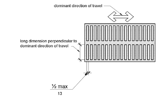
303.1 General. Where changes in level are permitted in floor or ground surfaces, they shall comply with 303.
EXCEPTIONS:
1. Animal containment areas shall not be required to comply with 303.
2. Areas of sport activity shall not be required to comply with 303.
303.2 Vertical. Changes in level of 1/4 inch (6.4 mm) high maximum shall be permitted to be vertical.
|
|
|
Figure 303.2 Vertical Change in Level |

303.3 Beveled. Changes in level between 1/4 inch (6.4 mm) high minimum and 1/2 inch (13 mm) high maximum shall be beveled with a slope not steeper than 1:2.
|
|
|
Figure 303.3 Beveled Change in Level |
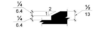
303.4 Ramps. Changes in level greater than 1/2 inch (13 mm) high shall be ramped, and shall comply with 405 or 406.
304.1 General. Turning space shall comply with 304.
304.2 Floor or Ground Surfaces. Floor or ground surfaces of a turning space shall comply with 302. Changes in level are not permitted.
EXCEPTION: Slopes not steeper than 1:48 shall be permitted.
304.3 Size. Turning space shall comply with 304.3.1 or 304.3.2.
304.3.1 Circular Space. The turning space shall be a space of 60 inches (1525 mm) diameter minimum. The space shall be permitted to include knee and toe clearance complying with 306.
304.3.2 T-Shaped Space. The turning space shall be a T-shaped space within a 60 inch (1525 mm) square minimum with arms and base 36 inches (915 mm) wide minimum. Each arm of the T shall be clear of obstructions 12 inches (305 mm) minimum in each direction and the base shall be clear of obstructions 24 inches (610 mm) minimum. The space shall be permitted to include knee and toe clearance complying with 306 only at the end of either the base or one arm.
|
|
|
Figure 304.3.2 T-Shaped Turning Space |
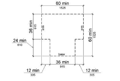
304.4 Door Swing. Doors shall be permitted to swing into turning spaces.
305 Clear Floor or Ground Space
305.1 General. Clear floor or ground space shall comply with 305.
305.2 Floor or Ground Surfaces. Floor or ground surfaces of a clear floor or ground space shall comply with 302. Changes in level are not permitted.
EXCEPTION: Slopes not steeper than 1:48 shall be permitted.
305.3 Size. The clear floor or ground space shall be 30 inches (760 mm) minimum by 48 inches (1220 mm) minimum.
|
|
|
Figure 305.3 Clear Floor or Ground Space |
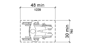
305.4 Knee and Toe Clearance. Unless otherwise specified, clear floor or ground space shall be permitted to include knee and toe clearance complying with 306.
305.5 Position. Unless otherwise specified, clear floor or ground space shall be positioned for either forward or parallel approach to an element.
|
|
|
Figure 305.5 Position of Clear Floor or Ground Space |
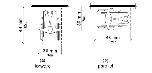
305.6 Approach. One full unobstructed side of the clear floor or ground space shall adjoin an accessible route or adjoin another clear floor or ground space.
305.7 Maneuvering Clearance. Where a clear floor or ground space is located in an alcove or otherwise confined on all or part of three sides, additional maneuvering clearance shall be provided in accordance with 305.7.1 and 305.7.2.
305.7.1 Forward Approach. Alcoves shall be 36 inches (915 mm) wide minimum where the depth exceeds 24 inches (610 mm).
|
|
|
Figure 305.7.1 Maneuvering Clearance in an Alcove, Forward Approach |
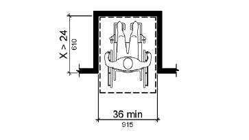
305.7.2 Parallel Approach. Alcoves shall be 60 inches (1525 mm) wide minimum where the depth exceeds 15 inches (380 mm).
|
|
|
Figure 305.7.2 Maneuvering Clearance in an Alcove, Parallel Approach |
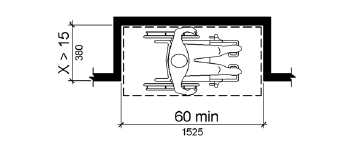
306.1 General. Where space beneath an element is included as part of clear floor or ground space or turning space, the space shall comply with 306. Additional space shall not be prohibited beneath an element but shall not be considered as part of the clear floor or ground space or turning space.
306.2 Toe Clearance.
306.2.1 General. Space under an element between the finish floor or ground and 9 inches (230 mm) above the finish floor or ground shall be considered toe clearance and shall comply with 306.2.
306.2.2 Maximum Depth. Toe clearance shall extend 25 inches (635 mm) maximum under an element.
306.2.3 Minimum Required Depth. Where toe clearance is required at an element as part of a clear floor space, the toe clearance shall extend 17 inches (430 mm) minimum under the element.
306.2.4 Additional Clearance. Space extending greater than 6 inches (150 mm) beyond the available knee clearance at 9 inches (230 mm) above the finish floor or ground shall not be considered toe clearance.
306.2.5 Width. Toe clearance shall be 30 inches (760
mm) wide minimum.
|
|
|
Figure 306.2 Toe Clearance |
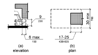
306.3 Knee Clearance.
306.3.1 General. Space under an element between 9 inches (230 mm) and 27 inches (685 mm) above the finish floor or ground shall be considered knee clearance and shall comply with 306.3.
306.3.2 Maximum Depth. Knee clearance shall extend 25 inches (635 mm) maximum under an element at 9 inches (230 mm) above the finish floor or ground.
306.3.3 Minimum Required Depth. Where knee clearance is required under an element as part of a clear floor space, the knee clearance shall be 11 inches (280 mm) deep minimum at 9 inches (230 mm) above the finish floor or ground, and 8 inches (205 mm) deep minimum at 27 inches (685 mm) above the finish floor or ground.
306.3.4 Clearance Reduction. Between 9 inches (230 mm) and 27 inches (685 mm) above the finish floor or ground, the knee clearance shall be permitted to reduce at a rate of 1 inch (25 mm) in depth for each 6 inches (150 mm) in height.
306.3.5 Width. Knee clearance shall be 30 inches (760
mm) wide minimum.
|
|
|
Figure 306.3 Knee Clearance |
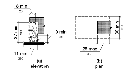
307.1 General. Protruding objects shall comply with 307.
307.2 Protrusion Limits. Objects with leading edges more than 27 inches (685 mm) and not more than 80 inches (2030 mm) above the finish floor or ground shall protrude 4 inches (100 mm) maximum horizontally into the circulation path.
EXCEPTION: Handrails shall be permitted to protrude 4 1/2 inches (115 mm) maximum.
|
|
|
Figure 307.2 Limits of Protruding Objects |
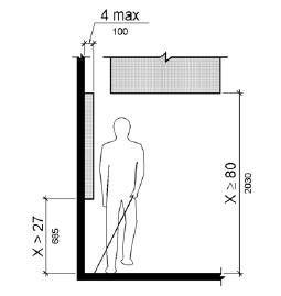
307.3 Post-Mounted Objects. Free-standing objects mounted on posts or pylons shall overhang circulation paths 12 inches (305 mm) maximum when located 27 inches (685 mm) minimum and 80 inches (2030 mm) maximum above the finish floor or ground. Where a sign or other obstruction is mounted between posts or pylons and the clear distance between the posts or pylons is greater than 12 inches (305 mm), the lowest edge of such sign or obstruction shall be 27 inches (685 mm) maximum or 80 inches (2030 mm) minimum above the finish floor or ground.
EXCEPTION: The sloping portions of handrails serving
stairs and ramps shall not be required to comply with 307.3.
|
|
|
Figure 307.3 Post-Mounted Protruding Objects |
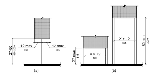
307.4 Vertical Clearance. Vertical clearance shall be 80 inches (2030 mm) high minimum. Guardrails or other barriers shall be provided where the vertical clearance is less than 80 inches (2030 mm) high. The leading edge of such guardrail or barrier shall be located 27 inches (685 mm) maximum above the finish floor or ground.
EXCEPTION: Door closers and door stops shall be
permitted to be 78 inches (1980 mm) minimum above the finish floor or ground.
|
|
|
Figure 307.4 Vertical Clearance |
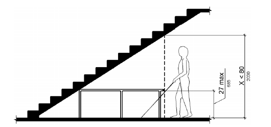
307.5 Required Clear Width. Protruding objects shall not reduce the clear width required for accessible routes.
308.1 General. Reach ranges shall comply with 308.
308.2 Forward Reach.
308.2.1 Unobstructed. Where a forward reach is
unobstructed, the high forward reach shall be 48 inches (1220 mm) maximum and
the low forward reach shall be 15 inches (380 mm) minimum above the finish
floor or ground.
|
|
|
Figure 308.2.1 Unobstructed Forward Reach |
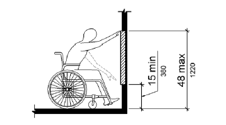
308.2.2 Obstructed High Reach. Where a high forward
reach is over an obstruction, the clear floor space shall extend beneath the element
for a distance not less than the required reach depth over the obstruction. The
high forward reach shall be 48 inches (1220 mm) maximum where the reach depth
is 20 inches (510 mm) maximum. Where the reach depth exceeds 20 inches (510
mm), the high forward reach shall be 44 inches (1120 mm) maximum and the reach
depth shall be 25 inches (635 mm) maximum.
|
|
|
Figure 308.2.2 Obstructed High Forward Reach |
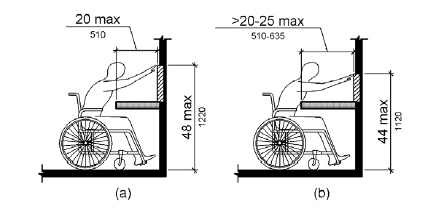
308.3 Side Reach.
308.3.1 Unobstructed. Where a clear floor or ground space allows a parallel approach to an element and the side reach is unobstructed, the high side reach shall be 48 inches (1220 mm) maximum and the low side reach shall be 15 inches (380 mm) minimum above the finish floor or ground.
EXCEPTIONS:
1. An obstruction shall be permitted between the clear floor or ground space and the element where the depth of the obstruction is 10 inches (255 mm) maximum.
2. Operable parts of fuel dispensers shall be permitted to be 54 inches (1370 mm) maximum measured from the surface of the vehicular way where fuel dispensers are installed on existing curbs.
|
|
|
Figure 308.3.1 Unobstructed Side Reach |
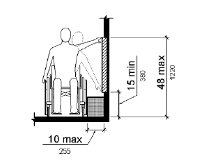
308.3.2 Obstructed High Reach. Where a clear floor or ground space allows a parallel approach to an element and the high side reach is over an obstruction, the height of the obstruction shall be 34 inches (865 mm) maximum and the depth of the obstruction shall be 24 inches (610 mm) maximum. The high side reach shall be 48 inches (1220 mm) maximum for a reach depth of 10 inches (255 mm) maximum. Where the reach depth exceeds 10 inches (255 mm), the high side reach shall be 46 inches (1170 mm) maximum for a reach depth of 24 inches (610 mm) maximum.
EXCEPTIONS:
1. The top of washing machines and clothes dryers shall be permitted to be 36 inches (915 mm) maximum above the finish floor.
2. Operable parts of fuel dispensers shall be permitted to be 54 inches (1370 mm) maximum measured from the surface of the vehicular way where fuel dispensers are installed on existing curbs.
|
|
|
Figure 308.3.2 Obstructed High Side Reach |
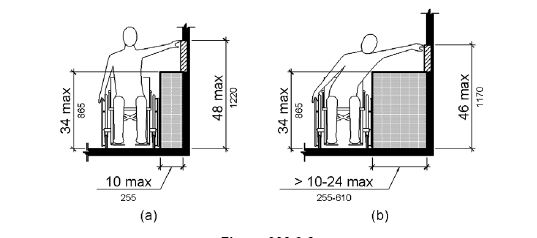
309.1 General. Operable parts shall comply with 309.
309.2 Clear Floor Space. A clear floor or ground space complying with 305 shall be provided.
309.3 Height. Operable parts shall be placed within one or more of the reach ranges specified in 308.
309.4 Operation. Operable parts shall be operable with one hand and shall not require tight grasping, pinching, or twisting of the wrist. The force required to activate operable parts shall be 5 pounds (22.2 N) maximum.
EXCEPTION: Gas pump nozzles shall not be required to
provide operable parts that have an activating force of 5 pounds (22.2
N) maximum.
401.1 Scope. The provisions of Chapter 4 shall apply where required by Chapter 2 or where referenced by a requirement in this document.
402.1 General. Accessible routes shall comply with 402.
402.2 Components. Accessible routes shall consist of one or more of the following components: walking surfaces with a running slope not steeper than 1:20, doorways, ramps, curb ramps excluding the flared sides, elevators, and platform lifts. All components of an accessible route shall comply with the applicable requirements of Chapter 4.
403.1 General. Walking surfaces that are a part of an accessible route shall comply with 403.
403.2 Floor or Ground Surface. Floor or ground surfaces shall comply with 302.
403.3 Slope. The running slope of walking surfaces shall not be steeper than 1:20. The cross slope of walking surfaces shall not be steeper than 1:48.
403.4 Changes in Level. Changes in level shall comply with 303.
403.5 Clearances. Walking surfaces shall provide clearances complying with 403.5.
EXCEPTION: Within employee work areas, clearances on common use circulation paths shall be permitted to be decreased by work area equipment provided that the decrease is essential to the function of the work being performed.
403.5.1 Clear Width. Except as provided in 403.5.2 and 403.5.3, the clear width of walking surfaces shall be 36 inches (915 mm) minimum.
EXCEPTION: The clear width shall be permitted to be reduced to 32 inches (815 mm) minimum for a length of 24 inches (610 mm) maximum provided that reduced width segments are separated by segments that are 48 inches (1220 mm) long minimum and 36 inches (915 mm) wide minimum.
|
|
|
Figure 403.5.1 Clear Width of an Accessible Route |
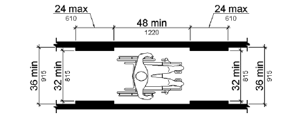
403.5.2 Clear Width at Turn. Where the accessible route makes a 180 degree turn around an element which is less than 48 inches (1220 mm) wide, clear width shall be 42 inches (1065 mm) minimum approaching the turn, 48 inches (1220 mm) minimum at the turn and 42 inches (1065 mm) minimum leaving the turn.
EXCEPTION: Where the clear width at the turn is 60 inches (1525 mm) minimum compliance with 403.5.2 shall not be required.
|
|
|
Figure 403.5.2 Clear Width at Turn |
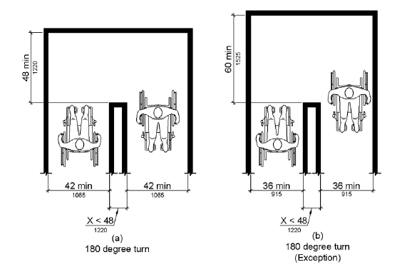
403.5.3 Passing Spaces. An accessible route with a clear width less than 60 inches (1525 mm) shall provide passing spaces at intervals of 200 feet (61 m) maximum. Passing spaces shall be either: a space 60 inches (1525 mm) minimum by 60 inches (1525 mm) minimum; or, an intersection of two walking surfaces providing a T-shaped space complying with 304.3.2 where the base and arms of the T-shaped space extend 48 inches (1220 mm) minimum beyond the intersection.
403.5.4 Aisle Width in Libraries. The clear width of aisles between stacks in libraries shall be 42 inches minimum (1065 mm).
EXCEPTION. In existing buildings and alterations, the minimum width shall be 36 inches (915 mm) minimum.
403.6 Handrails. Where handrails are provided along walking surfaces with running slopes not steeper than 1:20 they shall comply with 505.
404 Doors, Doorways, and Gates
404.1 General. Doors, doorways, and gates that are part of an accessible route shall comply with 404.
EXCEPTION: Doors, doorways, and gates designed to be operated only by security personnel shall not be required to comply with 404.2.7, 404.2.8, 404.2.9, 404.3.2 and 404.3.4 through 404.3.7.
404.2 Manual Doors, Doorways, and Manual Gates. Manual doors and doorways and manual gates intended for user passage shall comply with 404.2.
404.2.1 Revolving Doors, Gates, and Turnstiles. Revolving doors, revolving gates, and turnstiles shall not be part of an accessible route.
404.2.2 Double-Leaf Doors and Gates. At least one of the active leaves of doorways with two leaves shall comply with 404.2.3 and 404.2.4.
404.2.3 Clear Width. Door openings shall provide a clear width of 32 inches (815 mm) minimum. Clear openings of doorways with swinging doors shall be measured between the face of the door and the stop, with the door open 90 degrees. Openings more than 24 inches (610 mm) deep shall provide a clear opening of 36 inches (915 mm) minimum. There shall be no projections into the required clear opening width lower than 34 inches (865 mm) above the finish floor or ground. Projections into the clear opening width between 34 inches (865 mm) and 80 inches (2030 mm) above the finish floor or ground shall not exceed 4 inches (100 mm).
EXCEPTIONS:
1. In alterations, a projection of 5/8 inch (16 mm) maximum into the required clear width shall be permitted for the latch side stop.
2. Door closers and door stops shall be permitted to be 78 inches (1980 mm) minimum above the finish floor or ground.
|
|
|
Figure 404.2.3 Clear Width of Doorways |
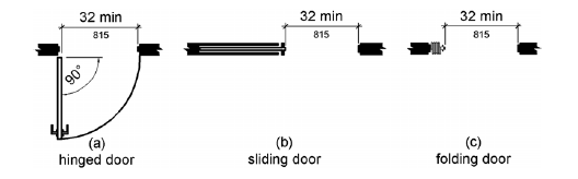
404.2.4 Maneuvering Clearances. Minimum maneuvering clearances at doors and gates shall comply with 404.2.4. Maneuvering clearances shall extend the full width of the doorway and the required latch side or hinge side clearance.
EXCEPTION: Entry doors to hospital patient rooms shall not be required to provide the clearance beyond the latch side of the door.
404.2.4.1 Swinging Doors and Gates. Swinging doors
and gates shall have maneuvering clearances complying with Table 404.2.4.1.
|
Table 404.2.4.1 Maneuvering Clearances at Manual Swinging Doors and Gates |
|||
|
Type of Use |
Minimum Maneuvering Clearance |
||
|
Approach Direction |
Door or Gate Side |
Perpendicular to Doorway |
Parallel to Doorway (beyond latch side unless noted) |
|
From front |
Pull |
60 inches (1525 mm) |
18 inches (455 mm) |
|
From front |
Push |
48 inches (1220 mm) |
0 inches (0 mm)1 |
|
From hinge side |
Pull |
60 inches (1525 mm) |
36 inches (915 mm) |
|
From hinge side |
Pull |
54 inches (1370 mm) |
42 inches (1065 mm) |
|
From hinge side |
Push |
42 inches (1065 mm)2 |
22 inches (560 mm)3 |
|
From latch side |
Pull |
48 inches (1220 mm)4 |
24 inches (610 mm) |
|
From latch side |
Push |
42 inches (1065 mm)4 |
24 inches (610 mm) |
|
Notes: 1. Add 12 inches (305 mm) if closer and latch are
provided. |
|||
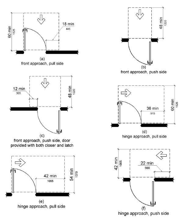
|
|
|
Figure 404.2.4.1 Maneuvering Clearances at Manual Swinging Doors and Gates |
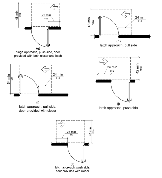
404.2.4.2 Doorways without Doors or Gates, Sliding Doors,
and Folding Doors. Doorways less than 36 inches (915 mm) wide without doors
or gates, sliding doors, or folding doors shall have maneuvering clearances
complying with Table 404.2.4.2.
|
Table 404.2.4.2 Maneuvering Clearances at Doorways without Doors or Gates, Manual Sliding Doors, and Manual Folding Doors |
||
|
|
Minimum Maneuvering Clearance |
|
|
Approach Direction |
Perpendicular to Doorway |
Parallel to Doorway (beyond stop/latch side unless noted) |
|
From Front |
48 inches (1220 mm) |
0 inches (0 mm) |
|
From side1 |
42 inches (1065 mm) |
0 inches (0 mm) |
|
From pocket/hinge side |
42 inches (1065 mm) |
22 inches (560 mm)2 |
|
From stop/latch side |
42 inches (1065 mm) |
24 inches (610 mm) |
|
Notes: 1. Doorway with no door only. |
||
|
|
|
Figure 404.2.4.2 Maneuvering Clearances at Doorways without Doors, Sliding Doors, Gates, and Folding Doors |
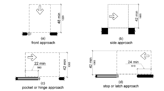
404.2.4.3 Recessed Doors and Gates. Maneuvering clearances for forward approach shall be provided when any obstruction within 18 inches (455 mm) of the latch side of a doorway projects more than 8 inches (205 mm) beyond the face of the door, measured perpendicular to the face of the door or gate.
|
|
|
Figure 404.2.4.3 Maneuvering Clearances at Recessed Doors and Gates |
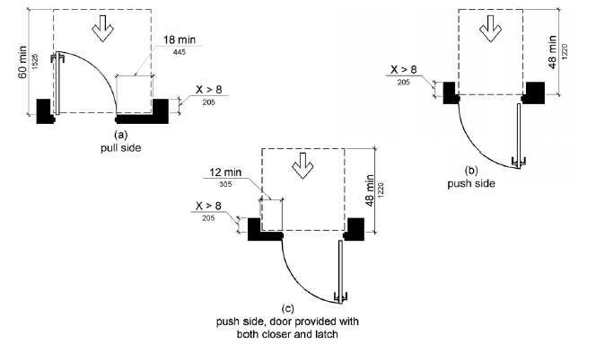
404.2.4.4 Floor or Ground Surface. Floor or ground surface within required maneuvering clearances shall comply with 302. Changes in level are not permitted.
EXCEPTIONS:
1. Slopes not steeper than 1:48 shall be permitted.
2. Changes in level at thresholds complying with 404.2.5 shall be permitted.
404.2.5 Thresholds. Thresholds, if provided at doorways, shall be 1/2 inch (13 mm) high maximum. Raised thresholds and changes in level at doorways shall comply with 302 and 303.
EXCEPTION: Existing or altered thresholds 3/4 inch (19 mm) high maximum that have a beveled edge on each side with a slope not steeper than 1:2 shall not be required to comply with 404.2.5.
404.2.6 Doors in Series and Gates in Series. The distance between two hinged or pivoted doors in series and gates in series shall be 48 inches (1220 mm) minimum plus the width of doors or gates swinging into the space.
|
|
|
Figure 404.2.6 Doors in Series and Gates in Series |
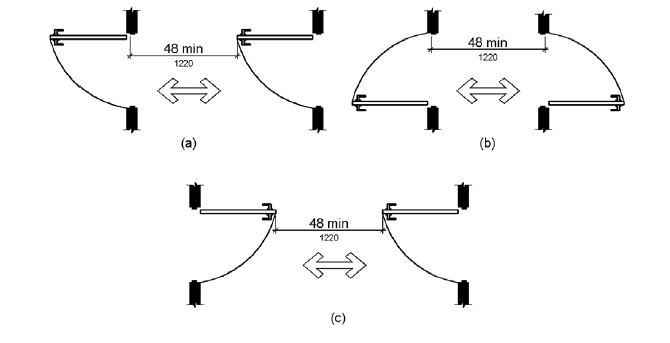
404.2.7 Door and Gate Hardware. Handles, pulls, latches, locks, and other operable parts on doors and gates shall comply with 309.4. Operable parts of such hardware shall be 34 inches (865 mm) minimum and 48 inches (1220 mm) maximum above the finish floor or ground.
Where sliding doors are in the fully open position, operating hardware shall be exposed and usable from both sides.
EXCEPTIONS:
1. Existing locks shall be permitted in any location at existing glazed doors without stiles, existing overhead rolling doors or grilles, and similar existing doors or grilles that are designed with locks that are activated only at the top or bottom rail.
2. Access gates in barrier walls and fences protecting pools, spas, and hot tubs shall be permitted to have operable parts of the release of latch on self-latching devices at 54 inches (1370 mm) maximum above the finish floor or ground provided the self-latching devices are not also self-locking devices and operated by means of a key, electronic opener, or integral combination lock.
404.2.8 Closing Speed. Door and gate closing speed shall comply with 404.2.8.
404.2.8.1 Door Closers and Gate Closers. Door closers and gate closers shall be adjusted so that from an open position of 90 degrees, the time required to move the door to a position of 12 degrees from the latch is 5 seconds minimum.
404.2.8.2 Spring Hinges. Door and gate spring hinges shall be adjusted so that from the open position of 70 degrees, the door or gate shall move to the closed position in 1.5 seconds minimum.
404.2.9 Door and Gate Opening Force. Fire doors shall have a minimum opening force allowable by the appropriate administrative authority. The force for pushing or pulling opens a door or gate other than fire doors shall be as follows:
1. Interior hinged doors and gates: 5 pounds (22.2 N) maximum.
2. Sliding or folding doors: 5 pounds (22.2 N) maximum.
3. Exterior hinged doors and gates: 8.5 pounds (37.8N)
These forces do not apply to the force required to retract latch bolts or disengage other devices that hold the door or gate in a closed position.
404.2.10 Door and Gate Surfaces. Swinging door and gate surfaces within 10 inches (255 mm) of the finish floor or ground measured vertically shall have a smooth surface on the push side extending the full width of the door or gate. Parts creating horizontal or vertical joints in these surfaces shall be within 1/16 inch (1.6 mm) of the same plane as the other. Cavities created by added kick plates shall be capped.
EXCEPTIONS:
1. Sliding doors shall not be required to comply with 404.2.10.
2. Tempered glass doors without stiles and having a bottom rail or shoe with the top leading edge tapered at 60 degrees minimum from the horizontal shall not be required to meet the 10 inch (255 mm) bottom smooth surface height requirement.
3. Doors and gates that do not extend to within 10 inches (255 mm) of the finish floor or ground shall not be required to comply with 404.2.10.
4. Existing doors and gates without smooth surfaces within 10 inches (255 mm) of the finish floor or ground shall not be required to provide smooth surfaces complying with 404.2.10 provided that if added kick plates are installed, cavities created by such kick plates are capped
404.2.11 Vision Lights. Doors, gates, and side lights adjacent to doors or gates, containing one or more glazing panels that permit viewing through the panels shall have the bottom of at least one glazed panel located 43 inches (1090 mm) maximum above the finish floor.
EXCEPTION: Vision lights with the lowest part more than 66 inches (1675 mm) from the finish floor or ground shall not be required to comply with 404.2.11.
404.3 Automatic and Power-Assisted Doors and Gates. Automatic doors and automatic gates shall comply with 404.3. Full-powered automatic doors shall comply with ANSI/BHMA A156.10 (incorporated by reference, see "Referenced Standards" in Chapter 1). Low-energy and power-assisted doors shall comply with ANSI/BHMA A156.19 (2002 edition) (incorporated by reference, see "Referenced Standards" in Chapter 1).
404.3.1 Clear Width. Doorways shall provide a clear opening of 32 inches (815 mm) minimum in power-on and power-off mode. The minimum clear width for automatic door systems in a doorway shall be based on the clear opening provided by all leaves in the open position.
404.3.2 Maneuvering Clearance. Clearances at power-assisted doors and gates shall comply with 404.2.4. Clearances at automatic doors and gates without standby power and serving an accessible means of egress shall comply with 404.2.4.
EXCEPTION: Where automatic doors and gates remain open in the power-off condition, compliance with 404.2.4 shall not be required.
404.3.3 Thresholds. Thresholds and changes in level at doorways shall comply with 404.2.5.
404.3.4 Doors in Series and Gates in Series. Doors in series and gates in series shall comply with 404.2.6.
404.3.5 Controls. Manually operated controls shall comply with 309. The clear floor space adjacent to the control shall be located beyond the arc of the door swing.
404.3.6 Break Out Opening. Where doors and gates without standby power are a part of a means of egress, the clear break out opening at swinging or sliding doors and gates shall be 32 inches (815 mm) minimum when operated in emergency mode.
EXCEPTION: Where manual swinging doors and gates comply with 404.2 and serve the same means of egress compliance with 404.3.6 shall not be required.
404.3.7 Revolving Doors, Revolving Gates, and Turnstiles. Revolving doors, revolving gates, and turnstiles shall not be part of an accessible route.
405.1 General. Ramps on accessible routes shall comply with 405.
EXCEPTION: In assembly areas, aisle ramp adjacent to seating and not serving elements required to be on an accessible route shall not be required to comply with 405.
405.2 Slope. Ramp runs shall have a running slope not steeper than 1:12.
EXCEPTION: In existing sites, buildings, and facilities, ramps shall be permitted to have running slopes steeper than 1:12 complying with Table 405.2 where such slopes are necessary due to space limitations.
|
Table 405.2 Maximum Ramp Slope and Rise for Existing Sites, Buildings, and Facilities |
|
|
Slope1 |
Maximum Rise |
|
Steeper than 1:10 but not steeper than 1:8 |
3 inches (75 mm) |
|
Steeper than 1:12 but not steeper than 1:10 |
6 inches (150 mm) |
|
Note: 1. A slope steeper than 1:8 is prohibited. |
|
405.3 Cross Slope. Cross slope of ramp runs shall not be steeper than 1:48.
405.4 Floor or Ground Surfaces. Floor or ground surfaces of ramp runs shall comply with 302. Changes in level other than the running slope and cross slope are not permitted on ramp runs.
405.5 Clear Width. The clear width of a ramp run and, where handrails are provided, the clear width between handrails shall be 36 inches (915 mm) minimum.
EXCEPTION: Within employee work areas, the required clear width of ramps that are a part of common use circulation paths shall be permitted to be decreased by work area equipment provided that the decrease is essential to the function of the work being performed.
405.6 Rise. The rise for any ramp run shall be 30 inches (760 mm) maximum.
405.7 Landings. Ramps shall have landings at the top and the bottom of each ramp run. Landings shall comply with 405.7.
|
|
|
Figure 405.7 Ramp Landings |
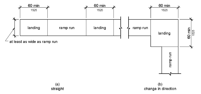
405.7.1 Slope. Landings shall comply with 302. Changes in level are not permitted.
EXCEPTION: Slopes not steeper than 1:48 shall be permitted.
405.7.2 Width. The landing clear width shall be at least as wide as the widest ramp run leading to the landing.
405.7.3 Length. The landing clear length shall be 60 inches (1525 mm) long minimum.
405.7.4 Change in Direction. Ramps that change direction between runs at landings shall have a clear landing 60 inches (1525 mm) minimum by 60 inches (1525 mm) minimum.
405.7.5 Doorways. Where doorways are located adjacent to a ramp landing, maneuvering clearances required by 404.2.4 and 404.3.2 shall be permitted to overlap the required landing area.
405.8 Handrails. Ramp runs with a rise greater than 6 inches (150 mm) shall have handrails complying with 505.
EXCEPTION: Within employee work areas, handrails shall not be required where ramps that are part of common use circulation paths are designed to permit the installation of handrails complying with 505. Ramps not subject to the exception to 405.5 shall be designed to maintain a 36 inch (915 mm) minimum clear width when handrails are installed.
405.9 Edge Protection. Edge protection complying with 405.9.1 or 405.9.2 shall be provided on each side of ramp runs and at each side of ramp landings.
EXCEPTIONS:
1. Edge protection shall not be required on ramps that are not required to have handrails and have sides complying with 406.3.
2. Edge protection shall not be required on the sides of ramp landings serving an adjoining ramp run or stairway.
3. Edge protection shall not be required on the sides of ramp landings having a vertical drop-off of 1/2 inch (13 mm) maximum within 10 inches (255 mm) horizontally of the minimum landing area specified in 405.7.
405.9.1 Extended Floor or Ground Surface. The floor or ground surface of the ramp run or landing shall extend 12 inches (305 mm) minimum beyond the inside face of a handrail complying with 505.
|
|
|
Figure 405.9.1 Extended Floor or Ground Surface Edge Protection |
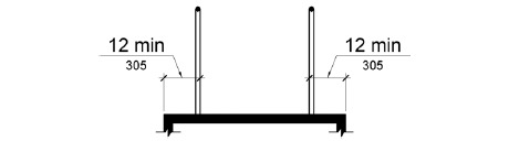
405.9.2 Curb or Barrier. A curb or barrier shall be provided that prevents the passage of a 4 inch (100 mm) diameter sphere, where any portion of the sphere is within 4 inches (100 mm) of the finish floor or ground surface.
|
|
|
Figure 405.9.2 Curb or Barrier Edge Protection |
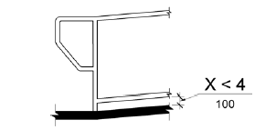
405.10 Wet Conditions. Landings subject to wet conditions shall be designed to prevent the accumulation of water.
406.1 General. Curb ramps on accessible routes shall comply with 406, 405.2 through 405.5, and 405.10.
406.2 Counter Slope. Counter slopes of adjoining
gutters and road surfaces immediately adjacent to the curb ramp
shall not be steeper than 1:20. The adjacent surfaces at transitions at curb
ramps to walks, gutters, and streets shall be at the same
level.
|
|
|
Figure 406.2 Counter Slope of Surfaces Adjacent to Curb Ramps |
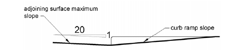
406.3 Sides of Curb Ramps. Where provided, curb ramp flares shall not be steeper than 1:10.
|
|
|
Figure 406.3 Sides of Curb Ramps |
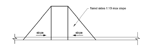
406.4 Landings. Landings complying with 405.7.1 shall be provided at the tops of curb ramps. The landing clear length shall be 36 inches (915 mm) minimum. The landing clear width shall be at least as wide as the curb ramp, excluding flared sides, leading to the landing.
EXCEPTION: In alterations, where there is no landing at the top of curb ramps, curb ramp flares shall be provided and shall not be steeper than 1:12.
|
|
|
Figure 406.4 Landings at the Top of Curb Ramps |
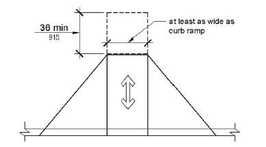
406.5 Location. Curb ramps and the flared sides of curb ramps shall be located so that they do not project into vehicular traffic lanes, parking spaces, or parking access aisles. Curb ramps at marked crossings shall be wholly contained within the markings, excluding any flared sides.
406.6 Diagonal Curb Ramps. Diagonal or corner type curb
ramps with returned curbs or other well-defined edges shall have the
edges parallel to the direction of pedestrian flow. The bottom of diagonal curb
ramps shall have a clear space 48 inches (1220 mm) minimum outside
active traffic lanes of the roadway. Diagonal curb ramps provided
at marked crossings shall provide the 48 inches (1220 mm) minimum
clear space within the markings. Diagonal curb ramps with flared
sides shall have a segment of curb 24 inches (610 mm) long minimum located on
each side of the curb ramp and within the marked crossing.
|
|
|
Figure 406.6 Diagonal or Corner Type Curb Ramps |
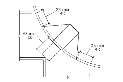
406.7 Islands. Raised islands in crossings shall be cut through level with the street or have curb ramps at both sides. Each curb ramp shall have a level area, with a slope of 1:48 maximum in all directions, that is 48 inches (1220 mm) long minimum by 36 inches (915 mm) wide minimum at the top of the curb ramp in the part of the island intersected by the crossings. Each 48 inch (1220 mm) minimum by 36 inch (915 mm) minimum area shall be oriented so that the 48 inch (1220 mm) minimum length is in the direction of the running slope of the curb ramp it serves. The 48 inch (1220 mm) minimum by 36 inch (915 mm) minimum areas and the accessible route shall be permitted to overlap.
|
|
|
Figure 406.7 Islands in Crossings |
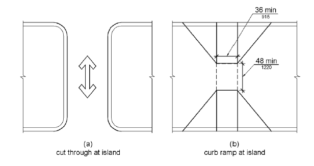
407.1 General. Elevators shall comply with 407 and with ASME A17.1 (incorporated by reference, see "Referenced Standards" in Chapter 1). They shall be passenger elevators as classified by ASME A17.1. Elevator operation shall be automatic.
407.2 Elevator Landing Requirements. Elevator landings shall comply with 407.2.
407.2.1 Call Controls. Where elevator call buttons or keypads are provided, they shall comply with 407.2.1 and 309.4. Call buttons shall be raised or flush.
EXCEPTION: Existing elevators shall be permitted to have recessed call buttons.
407.2.1.1 Height. Call buttons and keypads shall be located within one of the reach ranges specified in 308, measured to the centerline of the highest operable part.
EXCEPTION: Existing call buttons and existing keypads shall be permitted to be located at 54 inches (1370 mm) maximum above the finish floor, measured to the centerline of the highest operable part.
407.2.1.2 Size. Call buttons shall be 3/4 inch (19 mm) minimum in the smallest dimension.
EXCEPTION: Existing elevator call buttons shall not be required to comply with 407.2.1.2.
407.2.1.3 Clear Floor or Ground Space. A clear floor or ground space complying with 305 shall be provided at call controls.
407.2.1.4 Location. The call button that designates the up direction shall be located above the call button that designates the down direction.
EXCEPTION: Destination-oriented elevators shall not be required to comply with 407.2.1.4.
407.2.1.5 Signals. Call buttons shall have visible signals to indicate when each call is registered and when each call is answered.
EXCEPTIONS:
1. Destination-oriented elevators shall not be required to comply with 407.2.1.5 provided that visible and audible signals complying with 407.2.2 indicating which elevator car to enter are provided.
2. Existing elevators shall not be required to comply with 407.2.1.5.
407.2.1.6 Keypads. Where keypads are provided, keypads shall be in a standard telephone keypad arrangement and shall comply with 407.4.7.2.
407.2.2 Hall Signals. Hall signals, including in-car signals, shall comply with 407.2.2.
407.2.2.1 Visible and Audible Signals. A visible and audible signal shall be provided at each hoistway entrance to indicate which car is answering a call and the car's direction of travel. Where in-car signals are provided, they shall be visible from the floor area adjacent to the hall call buttons.
EXCEPTIONS:
1. Visible and audible signals shall not be required at each destination-oriented elevator where a visible and audible signal complying with 407.2.2 is provided indicating the elevator car designation information.
2. In existing elevators, a signal indicating the direction of car travel shall not be required.
407.2.2.2 Visible Signals. Visible signal fixtures shall be centered at 72 inches (1830 mm) minimum above the finish floor or ground. The visible signal elements shall be 2 1/2 inches (64 mm) minimum measured along the vertical centerline of the element. Signals shall be visible from the floor area adjacent to the hall call button.
EXCEPTIONS:
1. Destination-oriented elevators shall be permitted to have signals visible from the floor area adjacent to the hoistway entrance.
2. Existing elevators shall not be required to comply with 407.2.2.2.
|
|
|
Figure 407.2.2.2 Visible Hall Signals |
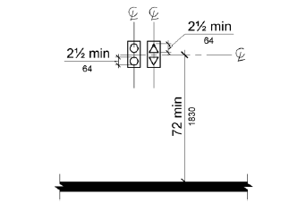
407.2.2.3 Audible Signals. Audible signals shall sound once for the up direction and twice for the down direction, or shall have verbal annunciators that indicate the direction of elevator car travel. Audible signals shall have a frequency of 1500 Hz maximum. Verbal annunciators shall have a frequency of 300 Hz minimum and 3000 Hz maximum. The audible signal and verbal annunciator shall be 10 dB minimum above ambient, but shall not exceed 80 dB, measured at the hall call button.
EXCEPTIONS:
1. Destination-oriented elevators shall not be required to comply with 407.2.2.3 provided that the audible tone and verbal announcement is the same as those given at the call button or call button keypad.
2. Existing elevators shall not be required to comply with the requirements for frequency and dB range of audible signals.
407.2.2.4 Differentiation. Each destination-oriented elevator in a bank of elevators shall have audible and visible means for differentiation.
407.2.3 Hoistway Signs. Signs at elevator hoistways shall comply with 407.2.3.
407.2.3.1 Floor Designation. Floor designations
complying with 703.2 and 703.4.1 shall be provided on both jambs of elevator
hoistway entrances. Floor designations shall be provided in both tactile
characters and braille. Tactile characters
shall be 2 inches (51 mm) high minimum. A tactile star shall be
provided on both jambs at the main entry level.
|
|
|
Figure 407.2.3.1 Floor Designations on Jambs of Elevator Hoistway Entrances |
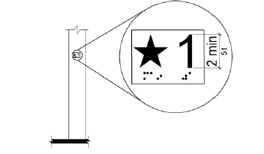
407.2.3.2 Car Designations. Destination-oriented
elevators shall provide tactile car identification complying with
703.2 on both jambs of the hoistway immediately below the floor designation.
Car designations shall be provided in both tactile characters
and braille. Tactile characters shall be 2 inches
(51 mm) high minimum.
|
|
|
Figure 407.2.3.2 Car Designations on Jambs of Destination-Oriented Elevator Hoistway Entrances |
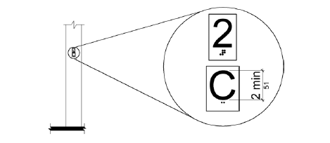
407.3 Elevator Door Requirements. Hoistway and car doors shall comply with 407.3.
407.3.1 Type. Elevator doors shall be the horizontal sliding type. Car gates shall be prohibited.
407.3.2 Operation. Elevator hoistway and car doors shall open and close automatically.
EXCEPTION: Existing manually operated hoistway swing doors shall be permitted provided that they comply with 404.2.3 and 404.2.9. Car door closing shall not be initiated until the hoistway door is closed.
407.3.3 Reopening Device. Elevator doors shall be provided with a reopening device complying with 407.3.3 that shall stop and reopen a car door and hoistway door automatically if the door becomes obstructed by an object or person.
EXCEPTION: Existing elevators with manually operated doors shall not be required to comply with 407.3.3.
407.3.3.1 Height. The device shall be activated by sensing an obstruction passing through the opening at 5 inches (125 mm) nominal and 29 inches (735 mm) nominal above the finish floor.
407.3.3.2 Contact. The device shall not require physical contact to be activated, although contact is permitted to occur before the door reverses.
407.3.3.3 Duration. Door reopening devices shall remain effective for 20 seconds minimum.
407.3.4 Door and Signal Timing. The minimum acceptable time from notification that a car is answering a call or notification of the car assigned at the means for the entry of destination information until the doors of that car start to close shall be calculated from the following equation:
T = D/(1.5 ft/s) or T = D/(455 mm/s) = 5 seconds minimum where T equals the total time in seconds and D equals the distance (in feet or millimeters) from the point in the lobby or corridor 60 inches (1525 mm) directly in front of the farthest call button controlling that car to the centerline of its hoistway door.
EXCEPTIONS:
1. For cars with in-car lanterns, T shall be permitted to begin when the signal is visible from the point 60 inches (1525 mm) directly in front of the farthest hall call button and the audible signal is sounded.
2. Destination-oriented elevators shall not be required to comply with 407.3.4.
407.3.5 Door Delay. Elevator doors shall remain fully open in response to a car call for 3 seconds minimum.
407.3.6 Width. The width of elevator doors shall comply with Table 407.4.1.
EXCEPTION: In existing elevators, a power-operated car door complying with 404.2.3 shall be permitted.
407.4 Elevator Car Requirements. Elevator cars shall comply with 407.4.
407.4.1 Car Dimensions. Inside dimensions of elevator cars and clear width of elevator doors shall comply with Table 407.4.1.
EXCEPTION: Existing elevator car configurations that provide a clear floor area of 16 square feet (1.5 m2) minimum and also provide an inside clear depth 54 inches (1370 mm) minimum and a clear width 36 inches (915 mm) minimum shall be permitted.
|
Table 407.4.1 Elevator Car Dimensions |
||||
|
Minimum Dimensions |
||||
|
Door Location |
Door Clear Width |
Inside Car, Side to Side |
Inside Car, Back Wall to Front Return |
Inside Car, Back Wall to Inside Face of Door |
|
Centered |
42 inches (1065 mm) |
80 inches (2030 mm) |
51 inches (1295 mm) |
54 inches (1370 mm) |
|
Side (off-centered) |
36 inches (915 mm)1 |
68 inches (1725 mm) |
51 inches (1295 mm) |
54 inches (1370 mm) |
|
Any |
36 inches (915 mm)1 |
54 inches (1370 mm) |
80 inches (2030 mm) |
80 inches (2030 mm) |
|
Any |
36 inches (915 mm)1 |
60 inches (1525 mm)2 |
60 inches (1525 mm)2 |
60 inches (1525 mm)2 |
|
Notes: 1. A tolerance of minus 5/8 inch (16 mm) is permitted. 2. Other car configurations that provide a turning space complying with 304 with the door closed shall be permitted. |
||||
|
|
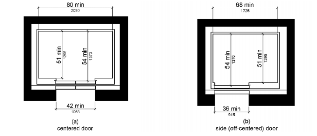
|
|
|
Figure 407.4.1 Elevator Car Dimensions |
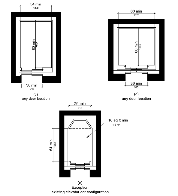
407.4.2 Floor Surfaces. Floor surfaces in elevator cars shall comply with 302 and 303.
407.4.3 Platform to Hoistway Clearance. The clearance between the car platform sill and the edge of any hoistway landing shall be 1 1/4 inch (32 mm) maximum.
407.4.4 Leveling. Each car shall be equipped with a self-leveling feature that will automatically bring and maintain the car at floor landings within a tolerance of 1/2 inch (13 mm) under rated loading to zero loading conditions.
407.4.5 Illumination. The level of illumination at the car controls, platform, car threshold and car landing sill shall be 5 foot candles (54 lux) minimum.
407.4.6 Elevator Car Controls. Where provided, elevator car controls shall comply with 407.4.6 and 309.4.
EXCEPTION: In existing elevators, where a new car operating panel complying with 407.4.6 is provided, existing car operating panels shall not be required to comply with 407.4.6.
407.4.6.1 Location. Controls shall be located within one of the reach ranges specified in 308.
EXCEPTIONS:
1. Where the elevator panel serves more than 16 openings and a parallel approach is provided, buttons with floor designations shall be permitted to be 54 inches (1370 mm) maximum above the finish floor.
2. In existing elevators, car control buttons with floor designations shall be permitted to be located 54 inches (1370 mm) maximum above the finish floor where a parallel approach is provided.
407.4.6.2 Buttons. Car control buttons with floor designations shall comply with 407.4.6.2 and shall be raised or flush.
EXCEPTION: In existing elevators, buttons shall be permitted to be recessed.
407.4.6.2.1 Size. Buttons shall be 3/4 inch (19 mm) minimum in their smallest dimension.
407.4.6.2.2 Arrangement. Buttons shall be arranged with numbers in ascending order. When two or more columns of buttons are provided they shall read from left to right.
407.4.6.3 Keypads. Car control keypads shall be in a standard telephone keypad arrangement and shall comply with 407.4.7.2.
407.4.6.4 Emergency Controls. Emergency controls shall comply with 407.4.6.4.
407.4.6.4.1 Height. Emergency control buttons shall have their centerlines 35 inches (890 mm) minimum above the finish floor.
407.4.6.4.2 Location. Emergency controls, including the emergency alarm, shall be grouped at the bottom of the panel.
407.4.7 Designations and Indicators of Car Controls. Designations and indicators of car controls shall comply with 407.4.7.
EXCEPTION: In existing elevators, where a new car operating panel complying with 407.4.7 is provided, existing car operating panels shall not be required to comply with 407.4.7.
407.4.7.1 Buttons. Car control buttons shall comply with 407.4.7.1.
407.4.7.1.1 Type. Control buttons shall be identified by tactile characters complying with 703.2.
407.4.7.1.2 Location. Raised character and braille designations shall be placed immediately to the left of the control button to which the designations apply.
EXCEPTION: Where space on an existing car operating panel precludes tactile markings to the left of the controls, markings shall be placed as near to the control as possible.
407.4.7.1.3 Symbols. The control button for the emergency stop, alarm, door open, door close, main entry floor, and phone, shall be identified with tactile symbols as shown in Table 407.4.7.1.3.
|
Table 407.4.7.1.3 Elevator Control Button Identification |
||
|
Control Button |
Tactile Symbol |
Braille Message |
|
Emergency Stop |
|
"ST"OP Three cells |
|
Alarm |
|
AL"AR"M Four cells |
|
Door Open |
|
OP"EN" Three cells |
|
Door Close |
|
CLOSE Five cells |
|
Main Entry Floor |
|
MA"IN" Three cells |
|
Phone |
|
PH"ONE" Four cells |
407.4.7.1.4 Visible Indicators. Buttons with floor designations shall be provided with visible indicators to show that a call has been registered. The visible indication shall extinguish when the car arrives at the designated floor.
407.4.7.2 Keypads. Keypads shall be identified by characters complying with 703.5 and shall be centered on the corresponding keypad button. The number five key shall have a single raised dot. The dot shall be 0.118 inch (3 mm) to 0.120 inch (3.05 mm) base diameter and in other aspects comply with Table 703.3.1.
407.4.8 Car Position Indicators. Audible and visible car position indicators shall be provided in elevator cars.
407.4.8.1 Visible Indicators. Visible indicators shall comply with 407.4.8.1.
407.4.8.1.1 Size. Characters shall be 1/2 inch (13 mm) high minimum.
407.4.8.1.2 Location. Indicators shall be located above the car control panel or above the door.
407.4.8.1.3 Floor Arrival. As the car passes a floor and when a car stops at a floor served by the elevator, the corresponding character shall illuminate.
EXCEPTION: Destination-oriented elevators shall not be required to comply with 407.4.8.1.3 provided that the visible indicators extinguish when the call has been answered.
407.4.8.1.4 Destination Indicator. In destination-oriented elevators, a display shall be provided in the car with visible indicators to show car destinations.
407.4.8.2 Audible Indicators. Audible indicators shall comply with 407.4.8.2.
407.4.8.2.1 Signal Type. The signal shall be an automatic verbal annunciator which announces the floor at which the car is about to stop.
EXCEPTION: For elevators other than destination-oriented elevators that have a rated speed of 200 feet per minute (1 m/s) or less, a non-verbal audible signal with a frequency of 1500 Hz maximum which sounds as the car passes or is about to stop at a floor served by the elevator shall be permitted.
407.4.8.2.2 Signal Level. The verbal annunciator shall be 10 dB minimum above ambient, but shall not exceed 80 dB, measured at the annunciator.
407.4.8.2.3 Frequency. The verbal annunciator shall have a frequency of 300 Hz minimum to 3000 Hz maximum.
407.4.9 Emergency Communication. Emergency two-way communication systems shall comply with 308. Tactile symbols and characters shall be provided adjacent to the device and shall comply with 703.2.
408 Limited-Use/Limited-Application Elevators
408.1 General. Limited-use/limited-application elevators shall comply with 408 and with ASME A17.1 (incorporated by reference, see "Referenced Standards" in Chapter 1). They shall be passenger elevators as classified by ASME A17.1. Elevator operation shall be automatic.
408.2 Elevator Landings. Landings serving limited-use/limited-application elevators shall comply with 408.2.
408.2.1 Call Buttons. Elevator call buttons and keypads shall comply with 407.2.1.
408.2.2 Hall Signals. Hall signals shall comply with 407.2.2.
408.2.3 Hoistway Signs. Signs at elevator hoistways shall comply with 407.2.3.1.
408.3 Elevator Doors. Elevator hoistway doors shall comply with 408.3.
408.3.1 Sliding Doors. Sliding hoistway and car doors shall comply with 407.3.1 through 407.3.3 and 408.4.1.
408.3.2 Swinging Doors. Swinging hoistway doors shall open and close automatically and shall comply with 404, 407.3.2 and 408.3.2.
408.3.2.1 Power Operation. Swinging doors shall be power-operated and shall comply with ANSI/BHMA A156.19 (2002 edition) (incorporated by reference, see "Referenced Standards" in Chapter 1).
408.3.2.2 Duration. Power-operated swinging doors shall remain open for 20 seconds minimum when activated.
408.4 Elevator Cars. Elevator cars shall comply with 408.4.
408.4.1 Car Dimensions and Doors. Elevator cars shall provide a clear width 42 inches (1065 mm) minimum and a clear depth 54 inches (1370 mm) minimum. Car doors shall be positioned at the narrow ends of cars and shall provide 32 inches (815 mm) minimum clear width.
EXCEPTIONS:
1. Cars that provide a clear width 51 inches (1295 mm) minimum shall be permitted to provide a clear depth 51 inches (1295 mm) minimum provided that car doors provide a clear opening 36 inches (915 mm) wide minimum.
2. Existing elevator cars shall be permitted to provide a clear width 36 inches (915 mm) minimum, clear depth 54 inches (1370 mm) minimum, and a net clear platform area 15 square feet (1.4 m2) minimum.
|
|
|
Figure 408.4.1 Limited-Use/Limited-Application (LULA) Elevator Car Dimensions |
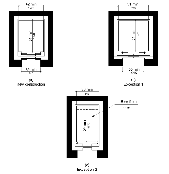
408.4.2 Floor Surfaces. Floor surfaces in elevator cars shall comply with 302 and 303.
408.4.3 Platform to Hoistway Clearance. The platform to hoistway clearance shall comply with 407.4.3.
408.4.4 Leveling. Elevator car leveling shall comply with 407.4.4.
408.4.5 Illumination. Elevator car illumination shall comply with 407.4.5.
408.4.6 Car Controls. Elevator car controls shall comply with 407.4.6. Control panels shall be centered on a side wall.
408.4.7 Designations and Indicators of Car Controls. Designations and indicators of car controls shall comply with 407.4.7.
408.4.8 Emergency Communications. Car emergency signaling devices complying with 407.4.9 shall be provided.
409 Private Residence Elevators
409.1 General. Private residence elevators that are provided within a residential dwelling unit required to provide mobility features complying with 809.2 through 809.4 shall comply with 409 and with ASME A17.1 (incorporated by reference, see "Referenced Standards" in Chapter 1). They shall be passenger elevators as classified by ASME A17.1. Elevator operation shall be automatic.
409.2 Call Buttons. Call buttons shall be 3/4 inch (19 mm) minimum in the smallest dimension and shall comply with 309.
409.3 Elevator Doors. Hoistway doors, car doors, and car gates shall comply with 409.3 and 404.
EXCEPTION: Doors shall not be required to comply with the maneuvering clearance requirements in 404.2.4.1 for approaches to the push side of swinging doors.
409.3.1 Power Operation. Elevator car and hoistway doors and gates shall be power operated and shall comply with ANSI/BHMA A156.19 (2002 edition) (incorporated by reference, see "Referenced Standards" in Chapter 1). Power operated doors and gates shall remain open for 20 seconds minimum when activated.
EXCEPTION: In elevator cars with more than one opening, hoistway doors and gates shall be permitted to be of the manual-open, self-close type.
409.3.2 Location. Elevator car doors or gates shall be positioned at the narrow end of the clear floor spaces required by 409.4.1.
409.4 Elevator Cars. Private residence elevator cars shall comply with 409.4.
409.4.1 Inside Dimensions of Elevator Cars. Elevator cars shall provide a clear floor space of 36 inches (915 mm) minimum by 48 inches (1220 mm) minimum and shall comply with 305.
409.4.2 Floor Surfaces. Floor surfaces in elevator cars shall comply with 302 and 303.
409.4.3 Platform to Hoistway Clearance. The clearance between the car platform and the edge of any landing sill shall be 1 1/2 inch (38 mm) maximum.
409.4.4 Leveling. Each car shall automatically stop at a floor landing within a tolerance of 1/2 inch (13 mm) under rated loading to zero loading conditions.
409.4.5 Illumination Levels. Elevator car illumination shall comply with 407.4.5.
409.4.6 Car Controls. Elevator car control buttons shall comply with 409.4.6, 309.3, 309.4, and shall be raised or flush.
409.4.6.1 Size. Control buttons shall be 3/4 inch (19 mm) minimum in their smallest dimension.
409.4.6.2 Location. Control panels shall be on a side wall, 12 inches (305 mm) minimum from any adjacent wall.
|
|
|
Figure 409.4.6.2 Location of Private Residence Elevator Control Panel |
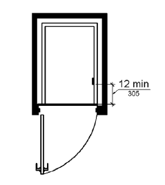
409.4.7 Emergency Communications. Emergency two-way communication systems shall comply with 409.4.7.
409.4.7.1 Type. A telephone and emergency signal device shall be provided in the car.
409.4.7.2 Operable Parts. The telephone and emergency signaling device shall comply with 309.3 and 309.4.
409.4.7.3 Compartment. If the telephone or device is in a closed compartment, the compartment door hardware shall comply with 309.
409.4.7.4 Cord. The telephone cord shall be 29 inches (735 mm) long minimum.
410.1 General. Platform lifts shall comply with ASME A18.1 (2011 edition) (incorporated by reference, see "Referenced Standards" in Chapter 1). Platform lifts shall not be attendant-operated and shall provide unassisted entry and exit from the lift.
410.2 Floor Surfaces. Floor surfaces in platform lifts shall comply with 302 and 303.
410.3 Clear Floor Space. Clear floor space in platform lifts shall comply with 305.
410.4 Platform to Runway Clearance. The clearance between the platform sill and the edge of any runway landing shall be 1 ¼ inch (32 mm) maximum.
410.5 Operable Parts. Controls for platform lifts shall comply with 309.
410.6 Doors and Gates. Platform lifts shall have low-energy power-operated doors or gates complying with 404.3. Doors shall remain open for 20 seconds minimum. End doors and gates shall provide a clear width 32 inches (815 mm) minimum. Side doors and gates shall provide a clear width 42 inches (1065 mm) minimum.
EXCEPTION: Platform lifts serving two landings maximum and having doors or gates on opposite sides shall be permitted to have self-closing manual doors or gates complying with 404.2.
|
|
|
Figure 410.6 Platform Lift Doors and Gates |
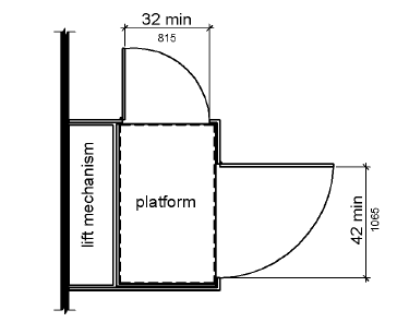
CHAPTER 5: GENERAL SITE AND BUILDING ELEMENTS
501.1 Scope. The provisions of Chapter 5 shall apply where required by Chapter 2 or where referenced by a requirement in this document.
502.1 General. Parking spaces shall comply with 502. Where parking spaces are marked with lines, width measurements of parking spaces and access aisles shall be made from the centerline of the markings.
EXCEPTION: Where parking spaces or access aisles are not adjacent to another parking space or access aisle, measurements shall be permitted to include the full width of the line defining the parking space or access aisle.
502.2 Vehicle Spaces. Vehicle parking spaces shall be either 8 feet (2440 mm) wide minimum or 11 feet (3350 mm) wide minimum, shall be marked to define the width, and shall have an adjacent access aisle complying with 502.3.
|
|
|
Figure 502.2 Vehicle Parking Spaces |
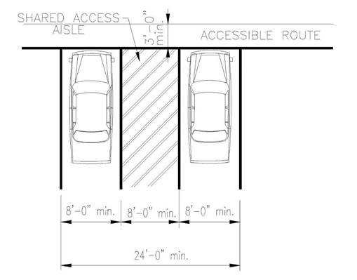
502.3 Access Aisle. Access aisles serving parking spaces shall comply with 502.3. Access aisles shall adjoin an accessible route. Two parking spaces shall be permitted to share a common access aisle.
EXCEPTION: Diagonal parking spaces shall not share an access aisle. Access aisles serving diagonal accessible parking spaces shall be located on the passenger side of the vehicle space.
|
|
|
Figure 502.3 (a) Parking Space Access Aisle
|
|
Figure 502.3 (b) Diagonal Parking Space Access Aisle |
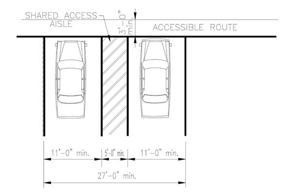
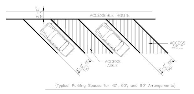
502.3.1 Width. The combined width of an accessible parking space and its adjacent access aisle shall be 16 feet (4875 mm) minimum. Access aisles serving parking spaces that are 11 feet (3350 mm) wide minimum shall be 5 feet (1525 mm) wide minimum. Access aisles serving parking spaces that are less than 11 feet (3350 mm) wide shall be 8 feet (2440 mm) wide minimum.
502.3.2 Length. Access aisles shall extend the full length of the parking spaces they serve.
502.3.3 Marking. Access aisles shall be marked with diagonal striping so as to discourage parking in them. A high quality yellow paint recommended by the paint manufacturer for pavement striping shall be used.
502.3.4 Location. Access aisles shall not overlap the vehicular way. Access aisles shall be permitted to be placed on either side of the parking space except for angled parking spaces required by 208.2.4 which shall have access aisles located on the passenger side of the parking spaces (see Figure 502.3 (b).
502.4 Floor or Ground Surfaces. Parking spaces and access aisles serving them shall comply with 302. Access aisles shall be at the same level as the parking spaces they serve. Changes in level are not permitted.
EXCEPTION: Slopes not steeper than 1:48 shall be permitted.
502.5 Vertical Clearance. Parking spaces required by 208.2.4, and access aisles and vehicular routes serving them, shall provide a vertical clearance of 98 inches (2490 mm) minimum.
502.6 Identification. Accessible parking spaces shall be designated as reserved by providing a permanently mounted R7-8 (U.S. Department of Transportation standard; see Figure 502.6 (a)) sign which contains the international symbol of accessibility. Such signs shall exhibit the dollar amount of the fine as required by the Illinois Vehicle Code [625 ILCS 5/1124 and 301.1] or the higher amount if required by local ordinance (see Figure 502.6 (b)). Signs shall be vertically mounted on a post or wall at front center of the parking space, no more than 6 feet (1830 mm) horizontally from the front of the parking space and set a minimum of 5 feet (1525 mm) and a maximum of 9 feet (2745 mm) from finished grade to the bottom of the R7-8 sign.
Accessible Parking Signs (for parking lots subject to the Illinois Vehicle Code) shall comply with the R7-8 sign shown in Figure 502.6(a) (U.S. Department of Transportation Standard). Existing signs may remain, but their useful lives shall not be extended by other means than normal maintenance.
|
|
|
Legend and Border—Pantone 340C International Symbol of Accessibility—White on Pantone 286 Background Background—White Reduce Spacing 80% |
|
Note: This is a standard sign and may be ordered from any traffic sign supplier by number. The arrow may be · Omitted if there is only one accessible space. · Made to point in one direction. · Replaced by a range of time such as "9 am-5 pm" where a part-time restriction exists. The sign must be supplemented with the Illinois Standard R7-I101 plate showing the mound of the fine for illegally parking in the reserved accessible space(s). |
|
Figure 502.6 (a) Parking Fine Sign |
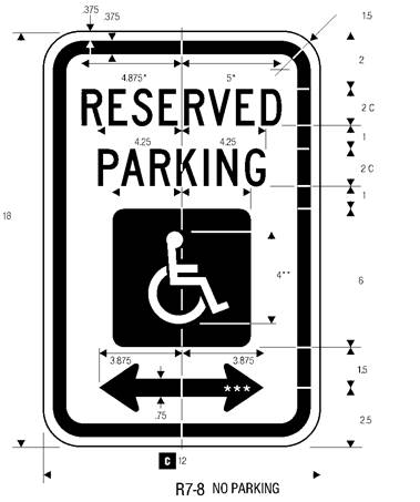
|
|
|
Figure 502.6 (b) Parking Sign |
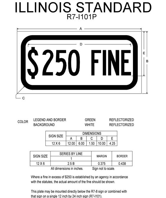
502.7 Relationship to Accessible Routes. Parking spaces and access aisles shall be designed so that vehicles, when parked, cannot obstruct the required clear width of adjacent accessible routes.
503.1 General. Passenger loading zones shall comply with 503.
503.2 Vehicle Pull-Up Space. Passenger loading zones shall provide a vehicular pull-up space 96 inches (2440 mm) wide minimum and 20 feet (6100 mm) long minimum.
503.3 Access Aisle. Passenger loading zones shall provide access aisles complying with 503 adjacent to the vehicle pull-up space. Access aisles shall adjoin an accessible route and shall not overlap the vehicular way.
503.3.1 Width. Access aisles serving vehicle pull-up spaces shall be 60 inches (1525 mm) wide minimum.
503.3.2 Length. Access aisles shall extend the full length of the vehicle pull-up spaces they serve.
503.3.3 Marking. Access aisles shall be marked so as
to discourage parking in them.
|
|
|
Figure 503.3 Passenger Loading Zone Access Aisle |
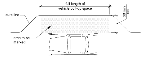
503.4 Floor and Ground Surfaces. Vehicle pull-up spaces and access aisles serving them shall comply with 302. Access aisles shall be at the same level as the vehicle pull-up space they serve. Changes in level are not permitted.
EXCEPTION: Slopes not steeper than 1:48 shall be permitted.
503.5 Vertical Clearance. Vehicle pull-up spaces, access aisles serving them, and a vehicular route from an entrance to the passenger loading zone, and from the passenger loading zone to a vehicular exit shall provide a vertical clearance of 114 inches (2895 mm) minimum.
504.1 General. Stairs shall comply with 504.
504.2 Treads and Risers. All steps on a flight of stairs shall have uniform riser heights and uniform tread depths. Risers shall be 4 inches (100 mm) high minimum and 7 inches (180 mm) high maximum. Treads shall be 11 inches (280 mm) deep minimum.
504.3 Open Risers. Open risers are not permitted.
504.4 Tread Surface. Stair treads shall comply with 302. Changes in level are not permitted.
EXCEPTION: Treads shall be permitted to have a slope not steeper than 1:48.
504.5 Nosings. The radius of curvature at the leading edge of the tread shall be 1/2 inch (13 mm) maximum. Nosings that project beyond risers shall have the underside of the leading edge curved or beveled. Risers shall be permitted to slope under the tread at an angle of 30 degrees maximum from vertical. The permitted projection of the nosing shall extend 1 1/2 inches (38 mm) maximum over the tread below.
|
|
|
Figure 504.5 Stair Nosings |
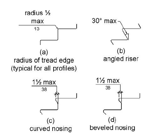
504.6 Handrails. Stairs shall have handrails complying with 505.
504.7 Wet Conditions. Stair treads and landings subject to wet conditions shall be designed to prevent the accumulation of water.
505.1 General. Handrails provided along walking surfaces complying with 403, required at ramps complying with 405, and required at stairs complying with 504 shall comply with 505.
505.2 Where Required. Handrails shall be provided on both sides of stairs and ramps.
EXCEPTION: In assembly areas, handrails shall not be required on both sides of aisle ramps where a handrail is provided at either side or within the aisle width.
505.3 Continuity. Handrails shall be continuous within the full length of each stair flight or ramp run. Inside handrails on switchback or dogleg stairs and ramps shall be continuous between flights or runs.
EXCEPTION: In assembly areas, handrails on ramps shall not be required to be continuous in aisles serving seating.
505.4 Height. Top of gripping surfaces of handrails shall be 34 inches (865 mm) minimum and 38 inches (965 mm) maximum vertically above walking surfaces, stair nosings, and ramp surfaces. Handrails shall be at a consistent height above walking surfaces, stair nosings, and ramp surfaces.
|
|
|
Figure 505.4 Handrail Height |
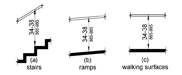
505.5 Clearance. Clearance between handrail gripping surfaces and adjacent surfaces shall be 1 1/2 inches (38 mm) minimum.
|
|
|
Figure 505.5 Handrail Clearance |
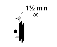
505.6 Gripping Surface. Handrail gripping surfaces shall be continuous along their length and shall not be obstructed along their tops or sides. The bottoms of handrail gripping surfaces shall not be obstructed for more than 20 percent of their length. Where provided, horizontal projections shall occur 1 1/2 inches (38 mm) minimum below the bottom of the handrail gripping surface.
EXCEPTIONS:
1. Where handrails are provided along walking surfaces with slopes not steeper than 1:20, the bottoms of handrail gripping surfaces shall be permitted to be obstructed along their entire length where they are integral to crash rails or bumper guards.
2. The distance between horizontal projections and the bottom of the gripping surface shall be permitted to be reduced by 1/8 inch (3.2 mm) for each 1/2 inch (13 mm) of additional handrail perimeter dimension that exceeds 4 inches (100 mm).
|
|
|
Figure 505.6 Horizontal Projections below Gripping Surface |
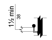
505.7 Cross Section. Handrail gripping surfaces shall have a cross section complying with 505.7.1 or 505.7.2.
505.7.1 Circular Cross Section. Handrail gripping surfaces with a circular cross section shall have an outside diameter of 1 1/4 inches (32 mm) minimum and 2 inches (51 mm) maximum.
505.7.2 Non-Circular Cross Sections. Handrail
gripping surfaces with a non-circular cross section shall have a perimeter
dimension of 4 inches (100 mm) minimum and 6 1/4 inches (160 mm) maximum, and a
cross-section dimension of 2 1/4 inches (57 mm) maximum.
|
|
|
Figure 505.7.2 Handrail Non-Circular Cross Section |
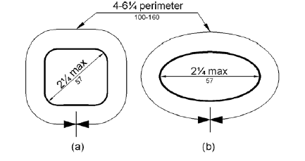
505.8 Surfaces. Handrail gripping surfaces and any surfaces adjacent to them shall be free of sharp or abrasive elements and shall have rounded edges.
505.9 Fittings. Handrails shall not rotate within their fittings.
505.10 Handrail Extensions. Handrail gripping surfaces shall extend beyond and in the same direction of stair flights and ramp runs in accordance with 505.10.
EXCEPTIONS:
1. Extensions shall not be required for continuous handrails at the inside turn of switchback or dogleg stairs and ramps.
2. In assembly areas, extensions shall not be required for ramp handrails in aisles serving seating where the handrails are discontinuous to provide access to seating and to permit crossovers within aisles.
3. In alterations, full extensions of handrails shall not be required where such extensions would be hazardous due to plan configuration.
505.10.1 Top and Bottom Extension at Ramps. Ramp handrails shall extend horizontally above the landing for 12 inches (305 mm) minimum beyond the top and bottom of ramp runs. Extensions shall return to a wall, guard, or the landing surface, or shall be continuous to the handrail of an adjacent ramp run.
|
|
|
Figure 505.10.1 Top and Bottom Handrail Extension at Ramps |
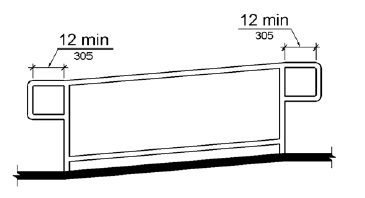
505.10.2 Top Extension at Stairs. At the top of a
stair flight, handrails shall extend horizontally above the landing for 12
inches (305 mm) minimum beginning directly above the first riser nosing.
Extensions shall return to a wall, guard, or the landing surface, or shall be
continuous to the handrail of an adjacent stair flight.
|
|
|
Figure 505.10.2 Top Handrail Extension at Stairs |
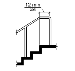
505.10.3 Bottom Extension at Stairs. At the bottom of a stair flight, handrails shall extend at the slope of the stair flight for a horizontal distance at least equal to one tread depth beyond the last riser nosing. Extension shall return to a wall, guard, or the landing surface, or shall be continuous to the handrail of an adjacent stair flight.
|
|
|
Figure 505.10.3 Bottom Handrail Extension at Stairs |
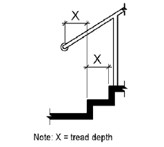
506 Accessible Means of Egress
506.1 Accessible Means of Egress Required. Accessible means of egress shall comply with this section. Accessible spaces shall be provided with not less than one accessible means of egress. Where more than one means of egress are required by the applicable building code from any accessible space, each accessible portion of the space shall be served by not less than two accessible means of egress.
EXCEPTIONS:
1. Accessible means of egress are not required to be provided in existing buildings.
2. One accessible means of egress is required from an accessible mezzanine level in accordance with 506.3, 506.4 or 506.5.
3. In assembly areas with ramped aisles or stepped aisles, one accessible means of egress is permitted where the common path of egress travel is accessible and meets the requirements of the applicable building code.
506.2 Continuity and Components. Each required accessible means of egress shall be continuous to a public way and shall consist of one or more of the following components:
1. Accessible routes complying with Chapter 4.
2. Interior exit stairways complying with 506.3 and the requirements of the applicable building code.
3. Exit access stairways complying with 506.3 and the requirements of the applicable building code.
4. Exterior exit stairways complying with 506.3 and the requirements of the applicable building code and serving levels other than the level of exit discharge.
5. Elevators complying with 407 and 506.4.
6. Platform lifts complying with 410 and 506.5.
7. Horizontal exits complying with the requirements of the applicable building code.
8. Ramps complying with 405 and the requirements of the applicable building code.
9. Areas of refuge complying with 506.6.
10. Exterior areas for assisted rescue complying with 506.7 serving exits at the level of exit discharge.
506.2.1 Elevators Required. In buildings where a required accessible floor is four or more stories above or below a level of exit discharge, not less than one required accessible means of egress shall be an elevator complying with 506.4.
EXCEPTIONS:
1. In buildings equipped throughout with a supervised automatic sprinkler system installed in accordance with the applicable building code, the elevator shall not be required on floors provided with a horizontal exit and located at or above the levels of exit discharge.
2. In buildings equipped throughout with a supervised automatic sprinkler system installed in accordance with the applicable building code, the elevator shall not be required on floors provided with a ramp complying with 405 and the requirements of the applicable building code.
506.3 Stairways. In order to be considered part of an accessible means of egress, a stairway between stories shall have a clear width of 48 inches (1219 mm) minimum between handrails and shall either incorporate an area of refuge within an enlarged floor-level landing or shall be accessed from an area of refuge complying with 506.6. Exit access stairways that connect levels in the same story are not permitted as part of an accessible means of egress.
EXCEPTIONS:
1. Exit access stairways providing means of egress from mezzanines are permitted as part of an accessible means of egress.
2. The clear width of 48 inches (1219 mm) between handrails is not required in buildings equipped throughout with a supervised automatic sprinkler system installed in accordance with the applicable building code.
3. The clear width of 48 inches (1219 mm) between handrails is not required for stairways accessed from an area of refuge in conjunction with a horizontal exit.
4. Areas of refuge are not required at exit access stairways where two-way communication is provided at the elevator landing in accordance with 506.8.
5. Areas of refuge are not required at stairways in buildings equipped throughout with a supervised automatic sprinkler system installed in accordance with the applicable building code.
6. Areas of refuge are not required at stairways serving open parking garages.
7. Areas of refuge are not required for smoke-protected assembly seating areas complying with the requirements of the applicable building code.
8. Areas of refuge are not required at stairways in residential multi-family occupancies.
9. Areas of refuge are not required for stairways accessed from a refuge area in conjunction with a horizontal exit.
506.4 Elevators. In order to be considered part of an accessible means of egress, an elevator shall comply with the emergency operation and signaling device requirements of Section 2.27 of ASME A17.1/CSA B44. Standby power complying with the requirements of the applicable building code shall be provided. The elevator shall be accessed from an area of refuge complying with 506.6.
EXCEPTIONS:
1. Areas of refuge are not required at the elevator in open parking garages.
2. Areas of refuge are not required in buildings and facilities equipped throughout with a supervised automatic sprinkler system installed in accordance with the applicable building code.
3. Areas of refuge are not required at elevators that are not required by the applicable building code to be located in a shaft.
4. Areas of refuge are not required at elevators serving smoke-protected assembly seating areas complying with the requirements of the applicable building code.
5. Areas of refuge are not required for elevators accessed from a refuge area in conjunction with a horizontal exit.
506.5 Platform Lifts. Platform lifts complying with 410 shall be permitted to serve as part of an accessible means of egress where allowed as part of a required accessible route in 506.8 except for Item 10. Standby power complying with the requirements of the applicable building code shall be provided for the platform lift.
506.6 Areas of Refuge. Every required area of refuge shall be accessible from the space it serves by an accessible means of egress.
506.6.1 Travel Distance. The maximum travel distance from any accessible space to an area of refuge shall not exceed the exit access travel distance permitted by the applicable building code for the occupancy.
506.6.2 Stairway or Elevator Access. Every required area of refuge shall have direct access to a stairway complying with 506.3 or an elevator complying with 506.4.
506.6.3 Size. Each area of refuge shall be sized to accommodate one wheelchair space of 30 inches by 48 inches (762 mm by 1219 mm) for each 200 occupants or portion thereof, based on the occupant load of the area of refuge and areas served by the area of refuge. Such wheelchair spaces shall not reduce the means of egress minimum width or required capacity. Access to any of the required wheelchair spaces in an area of refuge shall not be obstructed by more than one adjoining wheelchair space.
506.6.4 Separation. Each area of refuge shall be separated from the remainder of the story by a smoke barrier or a horizontal exit complying with the requirements of the applicable building code. Each area of refuge shall be designed to minimize the intrusion of smoke.
EXCEPTIONS:
1. Areas of refuge located within an enclosure for interior exit stairways complying with the requirements of the applicable building code.
2. Areas of refuge in outdoor facilities where exit access is essentially open to the outside.
506.6.5 Two-way Communication. Areas of refuge shall be provided with a two-way communication system complying with 506.8.1 and 506.8.2.
506.7 Exterior Areas for Assisted Rescue. Exterior areas for assisted rescue shall be accessed by an accessible route from the area served.
Where the exit discharge does not include an accessible route from an exit located on the level of exit discharge to a public way, an exterior area of assisted rescue shall be provided on the exterior landing in accordance with 506.7.1 through 506.7.4.
506.7.1 Size. Each exterior area for assisted rescue shall be sized to accommodate wheelchair spaces in accordance with 506.6.3.
506.7.2 Separation. Exterior walls separating the exterior area of assisted rescue from the interior of the building shall have a minimum fire-resistance rating of 1 hour, rated for exposure to fire from the inside. The fire-resistance-rated exterior wall construction shall extend horizontally 10 feet (3050 mm) beyond the landing on either side of the landing or equivalent fire-resistance-rated construction is permitted to extend out perpendicular to the exterior wall 4 feet (1220 mm) minimum on the side of the landing. The fire-resistance-rated construction shall extend vertically from the ground to a point 10 feet (3050 mm) above the floor level of the area for assisted rescue or to the roof line, whichever is lower. Openings within such fire-resistance-rated exterior walls shall be protected in accordance with the requirements of the applicable building code.
506.7.3 Openness. The exterior area for assisted rescue shall be open to the outside air. The sides other than the separation walls shall be not less than 50 percent open, and the open area shall be distributed so as to minimize the accumulation of smoke or toxic gases.
506.7.4 Stairways. Stairways that are part of the means of egress for the exterior area for assisted rescue shall provide a clear width of 48 inches (1220 mm) between handrails.
EXCEPTION. The clear width of 48 inches (1220 mm) between handrails is not required at stairways serving buildings equipped throughout with a supervised automatic sprinkler system installed in accordance with the applicable building code.
506.8 Two-Way Communication. A two-way communication system complying with 506.8.1 and 506.8.2 shall be provided at the landing serving each elevator or bank of elevators on each accessible floor that is one or more stories above or below the level of exit discharge.
EXCEPTIONS:
1. Two-way communication systems are not required at the landing serving each elevator or bank of elevators where the two-way communication system is provided within areas of refuge in accordance with 506.6.5.
2. Two-way communication systems are not required on floors provided with ramps complying with 405 and the requirements of the applicable building code.
3. Two-way communication systems are not required at the landings serving only service elevators that are not designated as part of the accessible means of egress or serve as part of the required accessible route into a facility.
4. Two-way communication systems are not required at the landings serving only freight elevators.
5. Two-way communication systems are not required at the landing serving a private residence elevator.
506.8.1 System Requirements. Two-way communication systems shall provide communication between each required location and the fire command center or a central control point location approved by the fire department. Where the central control point is not a constantly attended location, a two-way communication system shall have a timed automatic telephone dial-out capability to a monitoring location or 9-1-1. The two-way communication system shall include both audible and visible signals. If a handset is provided, the handset cords shall be 29 inches (735 mm) long minimum.
506.8.2 Directions. Directions for the use of the two-way communication system, instructions for summoning assistance via the two-way communication system and written identification of the location shall be posted adjacent to the two-way communication system. Signage shall comply with 703.5 for visual characters.
506.9 Signage. Signage indicating special accessibility provisions shall be provided as shown:
1. Each door providing access to an area of refuge from an adjacent floor area shall be identified by a sign stating: AREA OF REFUGE.
2. Each door providing access to an exterior area for assisted rescue shall be identified by a sign stating: EXTERIOR AREA FOR ASSISTED RESCUE.
Signage shall comply with 703.5 for visual characters and include the International Symbol of Accessibility. Where exit sign illumination is required by the applicable building code, the signs shall be illuminated. Additionally, visual characters, raised characters and braille signage complying with 703 shall be located at each door to an area of refuge and exterior area for assisted rescue in accordance with the requirements of the applicable building code.
506.10 Directional Signage. Directional signage indicating the location of all other means of egress and which of them are accessible means of egress shall be provided at the following:
1. At exits serving a required accessible space but not providing an approved accessible means of egress.
2. At elevator landings.
3. Within areas of refuge.
506.11 Instructions. In areas of refuge and exterior areas for assisted rescue, instructions on the use of the area under emergency conditions shall be posted. Signage shall comply with 703.5 for visual characters. The instructions shall include all of the following:
1. Persons able to use the exit stairway do so as soon as possible, unless they are assisting others.
2. Information on planned availability of assistance in the use of stairs or supervised operation of elevators and how to summon such assistance.
3. Directions for use of the two-way communication system where provided.
CHAPTER 6: PLUMBING ELEMENTS AND FACILITIES
601.1 Scope. The provisions of Chapter 6 shall apply where required by Chapter 2 or where referenced by a requirement in this document.
602.1 General. Drinking fountains shall comply with 307 and 602.
602.2 Clear Floor Space. Units shall have a clear floor or ground space complying with 305 positioned for a forward approach and centered on the unit. Knee and toe clearance complying with 306 shall be provided.
EXCEPTION: A parallel approach complying with 305 shall be permitted at units for children's use where the spout is 30 inches (760 mm) maximum above the finish floor or ground and is 3⅓ inches (90 mm) maximum from the front edge of the unit, including bumpers.
602.3 Operable Parts. Operable parts shall comply with 309.
602.4 Spout Height. Spout outlets shall be 36 inches (915 mm) maximum above the finish floor or ground.
602.5 Spout Location. The spout shall be located 15 inches (380 mm) minimum from the vertical support and 5 inches (125 mm) maximum from the front edge of the unit, including bumpers.
|
|
|
Figure 602.5 Drinking Fountain Spout Location |
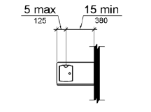
602.6 Water Flow. The spout shall provide a flow of water 4 inches (100 mm) high minimum and shall be located 5 inches (125 mm) maximum from the front of the unit. The angle of the water stream shall be measured horizontally relative to the front face of the unit. Where spouts are located less than 3 inches (75 mm) of the front of the unit, the angle of the water stream shall be 30 degrees maximum. Where spouts are located between 3 inches (75 mm) and 5 inches (125 mm) maximum from the front of the unit, the angle of the water stream shall be 15 degrees maximum.
602.7 Drinking Fountains for Standing Persons. Spout outlets of drinking fountains for standing persons shall be 38 inches (965 mm) minimum and 43 inches (1090 mm) maximum above the finish floor or ground.
603.1 General. Toilet and bathing rooms shall comply with 603.
603.2 Clearances. Clearances shall comply with 603.2.
603.2.1 Turning Space. Turning space complying with 304 shall be provided within the room.
603.2.2 Overlap. Required clear floor spaces, clearance at fixtures, and turning space shall be permitted to overlap.
603.2.3 Door Swing. Doors shall not swing into the clear floor space or clearance required for any fixture. Doors shall be permitted to swing into the required turning space.
EXCEPTIONS:
1. Doors to a toilet room or bathing room for a single occupant accessed only through a private office and not for common use or public use shall be permitted to swing into the clear floor space or clearance provided the swing of the door can be reversed to comply with 603.2.3.
2. Where the toilet room or bathing room is for individual use and a clear floor space complying with 305.3 is provided within the room beyond the arc of the door swing, doors shall be permitted to swing into the clear floor space or clearance required for any fixture. This exception shall also apply to toilet and bathing rooms within dwelling units required to comply with 812.
603.3 Mirrors. Mirrors located above lavatories or countertops shall be installed with the bottom edge of the reflecting surface 40 inches (1015 mm) maximum above the finish floor or ground. Mirrors not located above lavatories or countertops shall be installed with the bottom edge of the reflecting surface 35 inches (890 mm) maximum above the finish floor or ground.
603.4 Coat Hooks and Shelves. Coat hooks and shelves shall be located within one of the reach ranges specified in 308. Shelves shall be located 40 inches (1015 mm) minimum and 48 inches (1220 mm) maximum above the finish floor.
604 Water Closets and Toilet Compartments
604.1 General. Water closets and toilet compartments shall comply with 604.2 through 604.8.
EXCEPTION: Water closets and toilet compartments for children's use shall be permitted to comply with 604.9.
604.2 Location. The water closet shall be positioned with a wall or partition to the rear and to one side. The centerline of the water closet shall be 16 inches (405 mm) minimum to 18 inches (455 mm) maximum from the side wall or partition, except that the water closet shall be 17 inches (430 mm) minimum and 19 inches (485 mm) maximum from the side wall or partition in the ambulatory accessible toilet compartment specified in 604.8.2. Water closets shall be arranged for a left-hand or right-hand approach.
|
|
|
Figure 604.2 Water Closet Location |
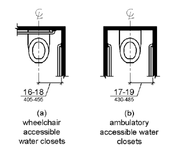
604.3 Clearance. Clearances around water closets and in toilet compartments shall comply with 604.3.
604.3.1 Size. Clearance around a water closet shall be 60 inches (1525 mm) minimum measured perpendicular from the side wall and 56 inches (1420 mm) minimum measured perpendicular from the rear wall.
|
|
|
Figure 604.3.1 Size of Clearance at Water Closets |
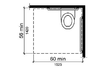
604.3.2 Overlap. The required clearance around the water closet shall be permitted to overlap the water closet, associated grab bars, dispensers, sanitary napkin disposal units, coat hooks, shelves, accessible routes, clear floor space and clearances required at other fixtures, and the turning space. No other fixtures or obstructions shall be located within the required water closet clearance.
EXCEPTION: In residential dwelling units required to comply with 809 and in multi-story housing required to comply with 812, a lavatory complying with 606 shall be permitted on the rear wall 18 inches (455 mm) minimum from the water closet centerline where the clearance at the water closet is 66 inches (1675 mm) minimum measured perpendicular from the rear wall.
|
|
|
Figure 604.3.2 (Exception) Overlap of Water Closet Clearance in Residential Dwelling Units |
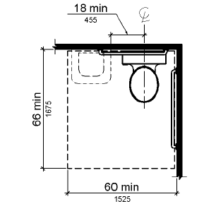
604.3.3 Changes in Level. Floor or ground surface within the required clearance shall comply with 302. Changes in level are not permitted.
EXCEPTION: Slopes not steeper than 1:48 shall be permitted.
604.4 Seats. The seat height of a water closet above the finish floor shall be 17 inches (430 mm) minimum and 19 inches (485 mm) maximum measured to the top of the seat. Seats shall not be sprung to return to a lifted position.
EXCEPTIONS:
1. A water closet in a toilet room for a single occupant accessed only through a private office and not for common use or public use shall not be required to comply with 604.4.
2. In residential dwelling units required to comply with 809 or 812, the height of water closets shall be permitted to be 15 inches (380 mm) minimum and 19 inches (485 mm) maximum above the finish floor measured to the top of the seat.
604.5 Grab Bars. Grab bars for water closets shall comply with 609. Grab bars shall be provided on the side wall closest to the water closet and on the rear wall.
EXCEPTIONS:
1. Grab bars shall not be required to be installed in a toilet room for a single occupant accessed only through a private office and not for common use or public use provided that reinforcement has been installed in walls and located so as to permit the installation of grab bars complying with 604.5.
2. In residential dwelling units required to comply with 809 and in multi-story housing required to comply with 812, grab bars shall not be required to be installed in toilet or bathrooms provided that reinforcement has been installed in walls and located so as to permit the installation of grab bars complying with 607.4.
3. In detention or correction facilities, grab bars shall not be required to be installed in housing or holding cells that are specially designed without protrusions for purposes of suicide prevention.
604.5.1 Side Wall. The side wall grab bar shall be 42 inches (1065 mm) long minimum, located 12 inches (305 mm) maximum from the rear wall and extending 54 inches (1370 mm) minimum from the rear wall.
|
|
|
Figure 604.5.1 Side Wall Grab Bar at Water Closets |
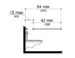
604.5.2 Rear Wall. The rear wall grab bar shall be 36 inches (915 mm) long minimum and extend from the centerline of the water closet 12 inches (305 mm) minimum on one side and 24 inches (610 mm) minimum on the other side.
EXCEPTIONS:
1. The rear grab bar shall be permitted to be 24 inches (610 mm) long minimum, centered on the water closet, where wall space does not permit a length of 36 inches (915 mm) minimum due to the location of a recessed fixture adjacent to the water closet.
2. Where an administrative authority requires flush controls for flush valves to be located in a position that conflicts with the location of the rear grab bar, then the rear grab bar shall be permitted to be split or shifted to the open side of the toilet area.
|
|
|
Figure 604.5.2 Rear Wall Grab Bar at Water Closets |
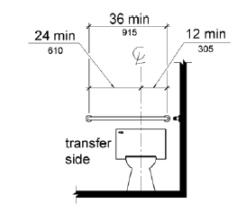
604.6 Flush Controls. Flush controls shall be hand operated or automatic. Hand operated flush controls shall comply with 309. Flush controls shall be located on the open side of the water closet except in ambulatory accessible compartments complying with 604.8.2.
604.7 Dispensers. Toilet paper dispensers shall comply with 309.4 and shall be 7 inches (180 mm) minimum and 9 inches (230 mm) maximum in front of the water closet measured to the centerline of the dispenser. The outlet of the dispenser shall be 15 inches (380 mm) minimum and 48 inches (1220 mm) maximum above the finish floor and shall not be located behind grab bars. Dispensers shall not be of a type that controls delivery or that does not allow continuous paper flow.
|
|
|
Figure 604.7 Dispenser Outlet Location |
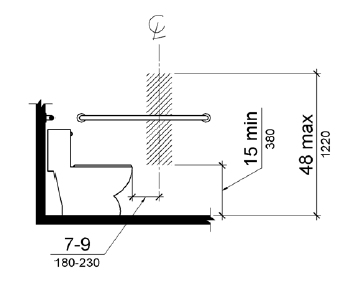
604.8 Toilet Compartments. Wheelchair accessible toilet compartments shall meet the requirements of 604.8.1 and 604.8.3. Compartments containing more than one plumbing fixture shall comply with 603. Ambulatory accessible compartments shall comply with 604.8.2 and 604.8.3.
604.8.1 Wheelchair Accessible Compartments. Wheelchair accessible compartments shall comply with 604.8.1.
604.8.1.1 Size. Wheelchair accessible compartments shall be 60 inches (1525 mm) wide minimum measured perpendicular to the side wall, and 56 inches (1420 mm) deep minimum for wall hung water closets and 59 inches (1500 mm) deep minimum for floor mounted water closets measured perpendicular to the rear wall. Wheelchair accessible compartments for children's use shall be 60 inches (1525 mm) wide minimum measured perpendicular to the side wall, and 59 inches (1500 mm) deep minimum for wall hung and floor mounted water closets measured perpendicular to the rear wall.
|
|
|
Figure 604.8.1.1 Size of Wheelchair Accessible Toilet Compartment |
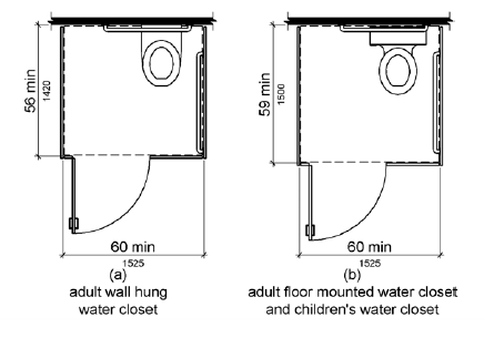
604.8.1.2 Doors. Toilet compartment doors, including door hardware, shall comply with 404 except that if the approach is to the latch side of the compartment door, clearance between the door side of the compartment and any obstruction shall be 42 inches (1065 mm) minimum. Doors shall be located in the front partition or in the side wall or partition farthest from the water closet. Where located in the front partition, the door opening shall be 4 inches (100 mm) maximum from the side wall or partition farthest from the water closet. Where located in the side wall or partition, the door opening shall be 4 inches (100 mm) maximum from the front partition. The door shall be self-closing. A door pull complying with 404.2.7 shall be placed on both sides of the door near the latch. Toilet compartment doors shall not swing into the minimum required compartment area.
|
|
|
Figure 604.8.1.2 Wheelchair Accessible Toilet Compartment Doors |
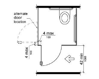
604.8.1.3 Approach. Compartments shall be arranged for left-hand or right-hand approach to the water closet.
604.8.1.4 Toe Clearance. The front partition and at least one side partition shall provide a toe clearance of 9 inches (230 mm) minimum above the finish floor and 6 inches (150 mm) deep minimum beyond the compartment-side face of the partition, exclusive of partition support members. Compartments for children's use shall provide a toe clearance of 12 inches (305 mm) minimum above the finish floor.
EXCEPTION: Toe clearance at the front partition is not required in a compartment greater than 62 inches (1575 mm) deep with a wall-hung water closet or 65 inches (1650 mm) deep with a floor-mounted water closet. Toe clearance at the side partition is not required in a compartment greater than 66 inches (1675 mm) wide. Toe clearance at the front partition is not required in a compartment for children's use that is greater than 65 inches (1650 mm) deep.
|
|
|
Figure 604.8.1.4 Wheelchair Accessible Toilet Compartment Toe Clearance |
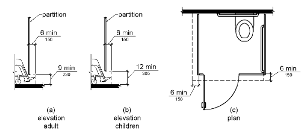
604.8.1.5 Grab Bars. Grab bars shall comply with 609. A side-wall grab bar complying with 604.5.1 shall be provided and shall be located on the wall closest to the water closet. In addition, a rear-wall grab bar complying with 604.5.2 shall be provided.
604.8.2 Ambulatory Accessible Compartments. Ambulatory accessible compartments shall comply with 604.8.2.
604.8.2.1 Size. Ambulatory accessible compartments shall have a depth of 60 inches (1525 mm) minimum and a width of 35 inches (890 mm) minimum and 37 inches (940 mm) maximum.
604.8.2.2 Doors. Toilet compartment doors, including door hardware, shall comply with 404, except that if the approach is to the latch side of the compartment door, clearance between the door side of the compartment and any obstruction shall be 42 inches (1065 mm) minimum. The door shall be self-closing. A door pull complying with 404.2.7 shall be placed on both sides of the door near the latch. Toilet compartment doors shall not swing into the minimum required compartment area.
604.8.2.3 Grab Bars. Grab bars shall comply with 609. A side-wall grab bar complying with 604.5.1 shall be provided on both sides of the compartment.
|
|
|
Figure 604.8.2 Ambulatory Accessible Toilet Compartment |
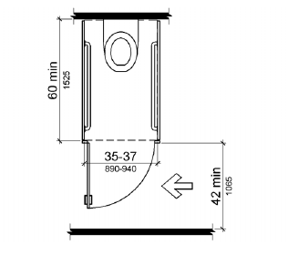
604.8.3 Coat Hooks and Shelves. Coat hooks shall be located within one of the reach ranges specified in 308. Shelves shall be located 40 inches (1015 mm) minimum and 48 inches (1220 mm) maximum above the finish floor.
604.9 Water Closets and Toilet Compartments for Children's Use. Water closets and toilet compartments for children's use shall comply with 604.9.
604.9.1 Location. The water closet shall be located with a wall or partition to the rear and to one side. The centerline of the water closet shall be 12 inches (305 mm) minimum and 18 inches (455 mm) maximum from the side wall or partition, except that the water closet shall be 17 inches (430 mm) minimum and 19 inches (485 mm) maximum from the side wall or partition in the ambulatory accessible toilet compartment specified in 604.8.2. Compartments shall be arranged for left-hand or right-hand approach to the water closet.
604.9.2 Clearance. Clearance around a water closet shall comply with 604.3.
604.9.3 Height. The height of water closets shall be 11 inches (280 mm) minimum and 17 inches (430 mm) maximum measured to the top of the seat. Seats shall not be sprung to return to a lifted position.
604.9.4 Grab Bars. Grab bars for water closets shall comply with 604.5.
604.9.5 Flush Controls. Flush controls shall be hand operated or automatic. Hand operated flush controls shall comply with 309.2 and 309.4 and shall be installed 36 inches (915 mm) maximum above the finish floor. Flush controls shall be located on the open side of the water closet except in ambulatory accessible compartments complying with 604.8.2.
604.9.6 Dispensers. Toilet paper dispensers shall comply with 309.4 and shall be 7 inches (180 mm) minimum and 9 inches (230 mm) maximum in front of the water closet measured to the centerline of the dispenser. The outlet of the dispenser shall be 14 inches (355 mm) minimum and 19 inches (485 mm) maximum above the finish floor. There shall be a clearance of 1 1/2 inches (38 mm) minimum below the grab bar. Dispensers shall not be of a type that controls delivery or that does not allow continuous paper flow.
604.9.7 Toilet Compartments. Toilet compartments shall comply with 604.8.
605.1 General. Urinals shall comply with 605.
605.2 Height and Depth. Urinals shall be the
stall-type or the wall-hung type with the rim 17 inches (430 mm) maximum above
the finish floor or ground. Urinals shall be 13 1/2 inches (345 mm) deep
minimum measured from the outer face of the urinal rim to the back of the
fixture.
|
|
|
Figure 605.2 Height and Depth of Urinals |
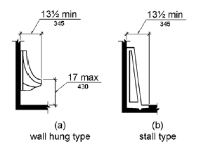
605.3 Clear Floor Space. A clear floor or ground space complying with 305 positioned for forward approach shall be provided.
605.4 Flush Controls. Flush controls shall be hand operated or automatic. Hand operated flush controls shall comply with 309.
606.1 General. Lavatories and sinks shall comply with 606.
606.2 Clear Floor Space. A clear floor space complying with 305, positioned for a forward approach, and knee and toe clearance complying with 306 shall be provided.
EXCEPTIONS:
1. A parallel approach complying with 305 shall be permitted to a kitchen sink in a space where a cook top or conventional range is not provided and to wet bars.
2. A lavatory in a toilet room or bathing facility for a single occupant accessed only through a private office and not for common use or public use shall not be required to provide knee and toe clearance complying with 306.
3. In residential dwelling units required to comply with 809 812, cabinetry shall be permitted under lavatories and kitchen sinks provided that all of the following conditions are met:
(a) the cabinetry can be removed without removal or replacement of the fixture;
(b) the finish floor extends under the cabinetry; and
(c) the walls behind and surrounding the cabinetry are finished.
4. A knee clearance of 24 inches (610 mm) minimum above the finish floor or ground shall be permitted at lavatories and sinks used primarily by children 6 through 12 years where the rim or counter surface is 31 inches (785 mm) maximum above the finish floor or ground.
5. A parallel approach complying with 305 shall be permitted to lavatories and sinks used primarily by children 5 years and younger.
6. The dip of the overflow shall not be considered in determining knee and toe clearances.
7. No more than one bowl of a multi-bowl sink shall be required to provide knee and toe clearance complying with 306.
606.3 Height. Lavatories and sinks shall be installed with the front of the higher of the rim or counter surface 34 inches (865 mm) maximum above the finish floor or ground.
EXCEPTIONS:
1. A lavatory in a toilet or bathing facility for a single occupant accessed only through a private office and not for common use or public use shall not be required to comply with 606.3.
2. In residential dwelling unit kitchens required to comply with 809 or 812, sinks that are adjustable to variable heights, 29 inches (735 mm) minimum and 36 inches (915 mm) maximum, shall be permitted where rough-in plumbing permits connections of supply and drain pipes for sinks mounted at the height of 29 inches (735 mm).
606.4 Faucets. Controls for faucets shall comply with 309. Hand-operated metering faucets shall remain open for 10 seconds minimum.
606.5 Exposed Pipes and Surfaces. Water supply and drain pipes under lavatories and sinks shall be insulated or otherwise configured to protect against contact. There shall be no sharp or abrasive surfaces under lavatories and sinks.
607.1 General. Bathtubs shall comply with 607.
607.2 Clearance. Clearance in front of bathtubs shall extend the length of the bathtub and shall be 30 inches (760 mm) wide minimum. A lavatory complying with 606 shall be permitted at the control end of the clearance. Where a permanent seat is provided at the head end of the bathtub, the clearance shall extend 12 inches (305 mm) minimum beyond the wall at the head end of the bathtub. Floor or ground surface within the required clearance shall comply with 302. Changes in level are not permitted.
EXCEPTION: Slopes not steeper than 1:48 shall be permitted.
|
|
|
Figure 607.2 Clearance for Bathtubs |
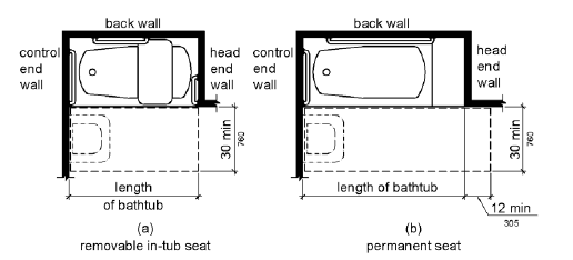
607.3 Seat. A permanent seat at the head end of the bathtub or a removable in-tub seat shall be provided. Seats shall comply with 610.
607.4 Grab Bars. Grab bars for bathtubs shall comply with 609 and shall be provided in accordance with 607.4.1 or 607.4.2.
EXCEPTIONS:
1. Grab bars shall not be required to be installed in a bathtub located in a bathing facility for a single occupant accessed only through a private office and not for common use or public use provided that reinforcement has been installed in walls and located so as to permit the installation of grab bars complying with 607.4.
2. In residential dwelling units required to comply with 809 and in multi-story housing required to comply with 812, grab bars shall not be required to be installed in bathtubs located in bathing facilities provided that reinforcement has been installed in walls and located so as to permit the installation of grab bars complying with 607.4.
607.4.1 Bathtubs with Permanent Seats. For bathtubs with permanent seats, grab bars shall be provided in accordance with 607.4.1.
607.4.1.1 Back Wall. Two grab bars shall be installed on the back wall, one located in accordance with 609.4 and the other located 8 inches (205 mm) minimum and 10 inches (255 mm) maximum above the rim of the bathtub. Each grab bar shall be installed 15 inches (380 mm) maximum from the head end wall and 12 inches (305 mm) maximum from the control end wall.
607.4.1.2 Control End Wall. A grab bar 24 inches (610 mm) long minimum shall be installed on the control end wall at the front edge of the bathtub.
|
|
|
Figure 607.4.1 Grab Bars for Bathtubs with Permanent Seats |
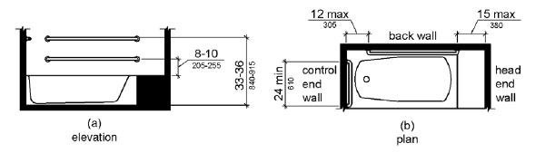
607.4.2 Bathtubs without Permanent Seats. For bathtubs without permanent seats, grab bars shall comply with 607.4.2.
607.4.2.1 Back Wall. Two grab bars shall be installed on the back wall, one located in accordance with 609.4 and other located 8 inches (205 mm) minimum and 10 inches (255 mm) maximum above the rim of the bathtub. Each grab bar shall be 24 inches (610 mm) long minimum and shall be installed 24 inches (610 mm) maximum from the head end wall and 12 inches (305 mm) maximum from the control end wall.
607.4.2.2 Control End Wall. A grab bar 24 inches (610 mm) long minimum shall be installed on the control end wall at the front edge of the bathtub.
607.4.2.3 Head End Wall. A grab bar 12 inches (305 mm) long minimum shall be installed on the head end wall at the front edge of the bathtub.
|
|
|
Figure 607.4.2 Grab Bars for Bathtubs with Removable In-Tub Seats |
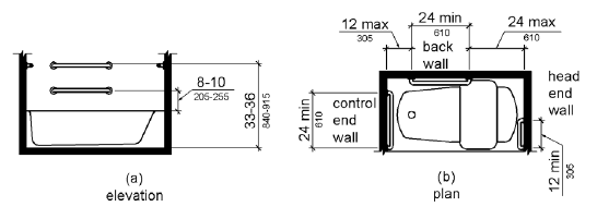
607.5 Controls. Controls, other than drain stoppers,
shall be located on an end wall. Controls shall be between the bathtub rim and
grab bar, and between the open side of the bathtub and the centerline of the
width of the bathtub. Controls shall comply with 309.4.
|
|
|
Figure 607.5 Bathtub Control Location |
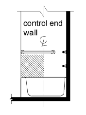
607.6 Shower Spray Unit and Water. A shower spray unit with a hose 59 inches (1500 mm) long minimum that can be used both as a fixed-position shower head and as a hand-held shower shall be provided. The shower spray unit shall be located within one or more of the reach ranges specified in 308. The shower spray unit shall have an on/off control with a non-positive shut-off. If an adjustable-height shower head on a vertical bar is used, the bar shall be installed so as not to obstruct the use of grab bars. Bathtub shower spray units shall deliver water that does not exceed the maximum temperature allowed by the Illinois Plumbing Code.
607.7 Bathtub Enclosures. Enclosures for bathtubs shall not obstruct controls, faucets, shower and spray units, or obstruct transfer from wheelchairs onto bathtub seats or into bathtubs. Enclosures on bathtubs shall not have tracks installed on the rim of the open face of the bathtub.
608.1 General. Shower compartments shall comply with 608.
608.2 Size and Clearances for Shower Compartments. Shower compartments shall have sizes and clearances complying with 608.2. Floor or ground surface within the required clearances shall comply with 302. Changes in level are not permitted.
EXCEPTION: Slopes not steeper than 1:48 shall be permitted.
608.2.1 Transfer Type Shower Compartments. Transfer type shower compartments shall be 36 inches (915 mm) by 36 inches (915 mm) clear inside dimensions measured at the center points of opposing sides and shall have a 36 inch (915 mm) wide minimum entry on the face of the shower compartment. Clearance of 36 inches (915 mm) wide minimum by 48 inches (1220 mm) long minimum measured from the control wall shall be provided.
|
|
|
Figure 608.2.1 Transfer Type Shower Compartment Size and Clearance |
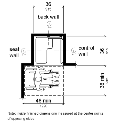
608.2.2 Standard Roll-In Type Shower Compartments. Standard roll-in type shower compartments shall be 30 inches (760 mm) wide minimum by 60 inches (1525 mm) deep minimum clear inside dimensions measured at center points of opposing sides and shall have a 60 inches (1525 mm) wide minimum entry on the face of the shower compartment.
608.2.2.1 Clearance. A 30 inch (760 mm) wide minimum by 60 inch (1525 mm) long minimum clearance shall be provided adjacent to the open face of the shower compartment.
EXCEPTION: A lavatory complying with 606 shall be permitted on one 30 inch (760 mm) wide minimum side of the clearance provided that it is not on the side of the clearance adjacent to the controls or, where provided, not on the side of the clearance adjacent to the shower seat.
|
|
|
Figure 608.2.2 Standard Roll-In Type Shower Compartment Size and Clearance |
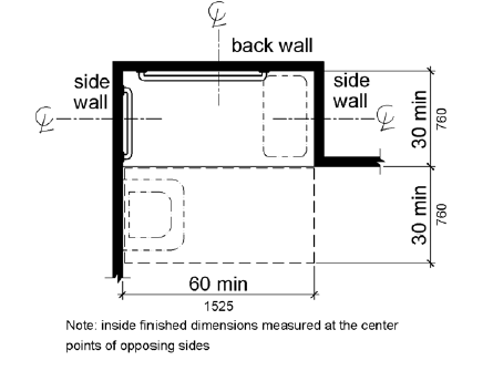
608.2.3 Alternate Roll-In Type Shower Compartments. Alternate roll-in type shower compartments shall be 36 inches (915 mm) wide and 60 inches (1525 mm) deep minimum clear inside dimensions measured at center points of opposing sides. A 36 inch (915 mm) wide minimum entry shall be provided at one end of the long side of the compartment.
|
|
|
Figure 608.2.3 Alternate Roll-In Type Shower Compartment Size and Clearance |
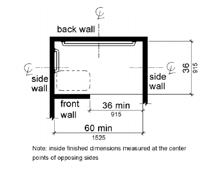
608.3 Grab Bars. Grab bars shall comply with 609 and shall be provided in accordance with 608.3. Where multiple grab bars are used, required horizontal grab bars shall be installed at the same height above the finish floor.
EXCEPTIONS:
1. Grab bars shall not be required to be installed in a shower located in a bathing facility for a single occupant accessed only through a private office, and not for common use or public use provided that reinforcement has been installed in walls and located so as to permit the installation of grab bars complying with 608.3.
2. In residential dwelling units required to comply with 809 and in multi-story housing required to comply with 812, grab bars shall not be required to be installed in showers located in bathing facilities provided that reinforcement has been installed in walls and located so as to permit the installation of grab bars complying with 608.3.
608.3.1 Transfer Type Shower Compartments. In transfer type compartments, grab bars shall be provided across the control wall and back wall to a point 18 inches (455 mm) from the control wall.
|
|
|
Figure 608.3.1 Grab Bars for Transfer Type Showers |
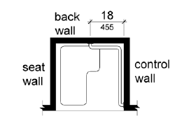
608.3.2 Standard Roll-In Type Shower Compartments. Where a seat is provided in standard roll-in type shower compartments, grab bars shall be provided on the back wall and the side wall opposite the seat. Grab bars shall not be provided above the seat. Where a seat is not provided in standard roll-in type shower compartments, grab bars shall be provided on three walls. Grab bars shall be installed 6 inches (150 mm) maximum from adjacent walls.
|
|
|
Figure 608.3.2 Grab Bars for Standard Roll-In Type Showers |
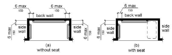
608.3.3 Alternate Roll-In Type Shower Compartments. In alternate roll-in type shower compartments, grab bars shall be provided on the back wall and the side wall farthest from the compartment entry. Grab bars shall not be provided above the seat. Grab bars shall be installed 6 inches (150 mm) maximum from adjacent walls.
|
|
|
Figure 608.3.3 Grab Bars for Alternate Roll-In Type Showers |
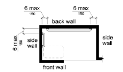
608.4 Seats. A folding or non-folding seat shall be provided in transfer type shower compartments. A folding seat shall be provided in roll-in type showers required in transient lodging guest rooms with mobility features complying with 806.2. Seats shall comply with 610.
EXCEPTION: In residential dwelling units required to comply with 809 and in multi-story housing required to comply with 812, seats shall not be required in transfer type shower compartments provided that reinforcement has been installed in walls so as to permit the installation of seats complying with 608.4.
608.5 Controls. Controls, faucets, and shower spray units shall comply with 309.4.
608.5.1 Transfer Type Shower Compartments. In transfer type shower compartments, the controls, faucets, and shower spray unit shall be installed on the side wall opposite the seat 38 inches (965 mm) minimum and 48 inches (1220 mm) maximum above the shower floor and shall be located on the control wall 15 inches (380 mm) maximum from the centerline of the seat toward the shower opening.
|
|
|
Figure 608.5.1 Transfer Type Shower Compartment Control Location |
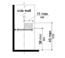
608.5.2 Standard Roll-In Type Shower Compartments. In standard roll-in type shower compartments, the controls, faucets, and shower spray unit shall be located above the grab bar, but no higher than 48 inches (1220 mm) above the shower floor. Where a seat is provided, the controls, faucets, and shower spray unit shall be installed on the back wall adjacent to the seat wall and shall be located 27 inches (685 mm) maximum from the seat wall.
|
|
|
Figure 608.5.2 Standard Roll-In Type Shower Compartment Control Location |
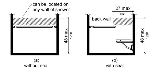
608.5.3 Alternate Roll-In Type Shower Compartments. In alternate roll-in type shower compartments, the controls, faucets, and shower spray unit shall be located above the grab bar, but no higher than 48 inches (1220 mm) above the shower floor. Where a seat is provided, the controls, faucets, and shower spray unit shall be located on the side wall adjacent to the seat 27 inches (685 mm) maximum from the side wall behind the seat or shall be located on the back wall opposite the seat 15 inches (380 mm) maximum, left or right, of the centerline of the seat. Where a seat is not provided, the controls, faucets, and shower spray unit shall be installed on the side wall farthest from the compartment entry.
|
|
|
Figure 608.5.3 Alternate Roll-In Type Shower Compartment Control Location |
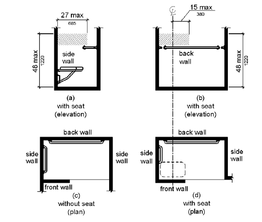
608.6 Shower Spray Unit and Water. A shower spray unit with a hose 59 inches (1500 mm) long minimum that can be used both as a fixed-position shower head and as a hand-held shower shall be provided. The shower spray unit shall have an on/off control with a non-positive shut-off. If an adjustable-height shower head on a vertical bar is used, the bar shall be installed so as not to obstruct the use of grab bars or shower controls. Shower spray units shall deliver water that does not exceed the maximum temperature allowed by the Illinois Plumbing Code.
EXCEPTION: A fixed shower head located at 48 inches (1220 mm) maximum above the shower finish floor shall be permitted instead of a hand-held spray unit in facilities that are not medical care facilities, long-term care facilities, transient lodging guest rooms, or residential dwelling units required to comply with 809 or 812.
608.7 Thresholds. Thresholds in roll-in type shower compartments shall be 1/2 inch (13 mm) high maximum in accordance with 303. In transfer type shower compartments, thresholds 1/2 inch (13 mm) high maximum shall be beveled, rounded, or vertical.
EXCEPTION: A threshold 2 inches (51 mm) high maximum shall be permitted in transfer type shower compartments in existing facilities where provision of a 1/2 inch (13 mm) high threshold would disturb the structural reinforcement of the floor slab.
608.8 Shower Enclosures. Enclosures for shower compartments shall not obstruct controls, faucets, and shower spray units or obstruct transfer from wheelchairs onto shower seats.
609.1 General. Grab bars in toilet facilities and bathing facilities shall comply with 609.
609.2 Cross Section. Grab bars shall have a cross section complying with 609.2.1 or 609.2.2.
609.2.1 Circular Cross Section. Grab bars with circular cross sections shall have an outside diameter of 1 1/4 inches (32 mm) minimum and 2 inches (51 mm) maximum.
609.2.2 Non-Circular Cross Section. Grab bars with non-circular cross sections shall have a cross-section dimension of 2 inches (51 mm) maximum and a perimeter dimension of 4 inches (100 mm) minimum and 4.8 inches (120 mm) maximum.
|
|
|
Figure 609.2.2 Grab Bar Non-Circular Cross Section |
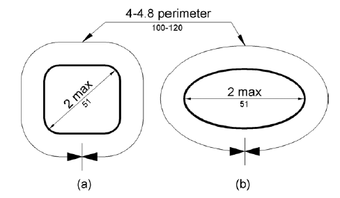
609.3 Spacing. The space between the wall and the grab bar shall be 1 1/2 inches (38 mm). The space between the grab bar and projecting objects below and at the ends shall be 1 1/2 inches (38 mm) minimum. The space between the grab bar and projecting objects above shall be 12 inches (305 mm) minimum.
EXCEPTION: The space between the grab bars and shower controls, shower fittings, and other grab bars above shall be permitted to be 1 1/2 inches (38 mm) minimum.
|
|
|
Figure 609.3 Spacing of Grab Bars |
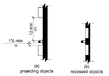
609.4 Position of Grab Bars. Grab bars shall be installed in a horizontal position, 33 inches (840 mm) minimum and 36 inches (915 mm) maximum above the finish floor measured to the top of the gripping surface, except that at water closets for children's use complying with 604.9, grab bars shall be installed in a horizontal position 18 inches (455 mm) minimum and 27 inches (685 mm) maximum above the finish floor measured to the top of the gripping surface. The height of the lower grab bar on the back wall of a bathtub shall comply with 607.4.1.1 or 607.4.2.1.
609.5 Surface Hazards. Grab bars and any wall or other surfaces adjacent to grab bars shall be free of sharp or abrasive elements and shall have rounded edges.
609.6 Fittings. Grab bars shall not rotate within their fittings.
609.7 Installation. Grab bars shall be installed in any manner that provides a gripping surface at the specified locations and that does not obstruct the required clear floor space.
609.8 Structural Strength. Allowable stresses shall not be exceeded for materials used when a vertical or horizontal force of 250 pounds (1112 N) is applied at any point on the grab bar, fastener, mounting device, or supporting structure.
610.1 General. Seats in bathtubs and shower compartments shall comply with 610.
610.2 Bathtub Seats. The top of bathtub seats shall be 17 inches (430 mm) minimum and 19 inches (485 mm) maximum above the bathroom finish floor. The depth of a removable in-tub seat shall be 15 inches (380 mm) minimum and 16 inches (405 mm) maximum. The seat shall be capable of secure placement. Permanent seats at the head end of the bathtub shall be 15 inches (380 mm) deep minimum and shall extend from the back wall to or beyond the outer edge of the bathtub.
|
|
|
Figure 610.2 Bathtub Seats |
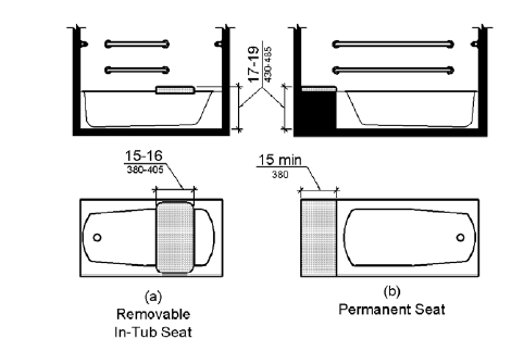
610.3 Shower Compartment Seats. Where a seat is provided in a standard roll-in shower compartment, it shall be a folding type, shall be installed on the side wall adjacent to the controls, and shall extend from the back wall to a point within 3 inches (75 mm) of the compartment entry. Where a seat is provided in an alternate roll-in type shower compartment, it shall be a folding type, shall be installed on the front wall opposite the back wall, and shall extend from the adjacent side wall to a point within 3 inches (75 mm) of the compartment entry. In transfer-type showers, the seat shall extend from the back wall to a point within 3 inches (75 mm) of the compartment entry. The top of the seat shall be 17 inches (430 mm) minimum and 19 inches (485 mm) maximum above the bathroom finish floor. Seats shall comply with 610.3.1 or 610.3.2.
|
|
|
Figure 610.3 Extent of Seat |
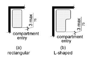
610.3.1 Rectangular Seats. The rear edge of a rectangular seat shall be 2 1/2 inches (64 mm) maximum and the front edge 15 inches (380 mm) minimum and 16 inches (405 mm) maximum from the seat wall. The side edge of the seat shall be 1 1/2 inches (38 mm) maximum from the adjacent wall.
|
|
|
Figure 610.3.1 Rectangular Shower Seat |
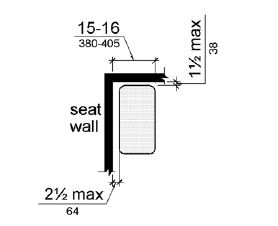
610.3.2 L-Shaped Seats. The rear edge of an L-shaped seat shall be 2 1/2 inches (64 mm) maximum and the front edge 15 inches (380 mm) minimum and 16 inches (405 mm) maximum from the seat wall. The rear edge of the "L" portion of the seat shall be 1 1/2 inches (38 mm) maximum from the wall and the front edge shall be 14 inches (355 mm) minimum and 15 inches (380 mm) maximum from the wall. The end of the "L" shall be 22 inches (560 mm) minimum and 23 inches maximum (585 mm) from the main seat wall.
|
|
|
Figure 610.3.2 L-Shaped Shower Seat |
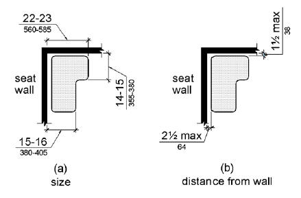
610.4 Structural Strength. Allowable stresses shall not be exceeded for materials used when a vertical or horizontal force of 250 pounds (1112 N) is applied at any point on the seat, fastener, mounting device, or supporting structure.
611 Washing Machines and Clothes Dryers
611.1 General. Washing machines and clothes dryers shall comply with 611.
611.2 Clear Floor Space. A clear floor or ground space complying with 305 positioned for parallel approach shall be provided. For top loading machines, the clear floor or ground space shall be centered on the appliance. For front loading machines, the clear floor or ground space shall be offset 24 inches (610 mm) maximum from the centerline of the door opening.
611.3 Operable Parts. Operable parts, including doors, lint screens, and detergent and bleach compartments shall comply with 309.
611.4 Height. Top loading machines shall have the door to the laundry compartment located 36 inches (915 mm) maximum above the finish floor. Front loading machines shall have the bottom of the opening to the laundry compartment located 15 inches (380 mm) minimum and 36 inches (915 mm) maximum above the finish floor.
|
|
|
Figure 611.4 Height of Laundry Compartment Opening |
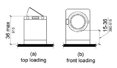
612.1 General. Saunas and steam rooms shall comply with 612.
612.2 Bench. Where seating is provided in saunas and steam rooms, at least one bench shall comply with 903. Doors shall not swing into the clear floor space required by 903.2.
EXCEPTION: A readily removable bench shall be permitted to obstruct the turning space required by 612.3 and the clear floor or ground space required by 903.2.
612.3 Turning Space. A turning space complying with 304 shall be provided within saunas and steam rooms.
CHAPTER 7: COMMUNICATION ELEMENTS AND FEATURES
701.1 Scope. The provisions of Chapter 7 shall apply where required by Chapter 2 or where referenced by a requirement in this document.
702.1 General. Fire alarm systems shall have permanently installed audible and visible alarms complying with NFPA 72 (2013 edition) (incorporated by reference, see "Referenced Standards" in Chapter 1). In addition, alarms in guest rooms required to provide communication features shall comply with sections 18.4 and 18.5 of NFPA 72 (2013 edition).
EXCEPTION: Fire alarm systems in medical care facilities shall be permitted to be provided in accordance with industry practice.
703.1 General. Signs shall comply with 703. Where both visual and tactile characters are required, either one sign with both visual and tactile characters, or two separate signs, one with visual, and one with tactile characters, shall be provided.
703.2 Raised Characters. Raised characters shall comply with 703.2 and shall be duplicated in braille complying with 703.3. Raised characters shall be installed in accordance with 703.4.
703.2.1 Depth. Raised characters shall be 1/32 inch (0.8 mm) minimum above their background.
703.2.2 Case. Characters shall be uppercase.
703.2.3 Style. Characters shall be sans serif. Characters shall not be italic, oblique, script, highly decorative, or of other unusual forms.
703.2.4 Character Proportions. Characters shall be selected from fonts where the width of the uppercase letter "O" is 55 percent minimum and 110 percent maximum of the height of the uppercase letter "I".
703.2.5 Character Height. Character height measured vertically from the baseline of the character shall be 5/8 inch (16 mm) minimum and 2 inches (51 mm) maximum based on the height of the uppercase letter "I".
EXCEPTION: Where separate raised and visual characters with the same information are provided, raised character height shall be permitted to be 1/2 inch (13 mm) minimum.
|
|
|
Figure 703.2.5 Height of Raised Characters |
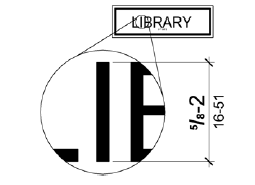
703.2.6 Stroke Thickness. Stroke thickness of the uppercase letter "I" shall be 15 percent maximum of the height of the character.
703.2.7 Character Spacing. Character spacing shall be measured between the two closest points of adjacent raised characters within a message, excluding word spaces. Where characters have rectangular cross sections, spacing between individual raised characters shall be 1/8 inch (3.2 mm) minimum and 4 times the raised character stroke width maximum. Where characters have other cross sections, spacing between individual raised characters shall be 1/16 inch (1.6 mm) minimum and 4 times the raised character stroke width maximum at the base of the cross sections, and 1/8 inch (3.2 mm) minimum and 4 times the raised character stroke width maximum at the top of the cross sections. Characters shall be separated from raised borders and decorative elements 3/8 inch (9.5 mm) minimum.
703.2.8 Line Spacing. Spacing between the baselines of separate lines of raised characters within a message shall be 135 percent minimum and 170 percent maximum of the raised character height.
703.3 Braille. Braille shall be contracted (Grade 2) and shall comply with 703.3 and 703.4.
703.3.1 Dimensions and Capitalization. Braille dots shall have a domed or rounded shape and shall comply with Table 703.3.1. The indication of an uppercase letter or letters shall only be used before the first word of sentences, proper nouns and names, individual letters of the alphabet, initials, and acronyms.
|
Table 703.3.1 Braille Dimensions |
|
|
Measurement Range |
Minimum in
Inches |
|
Dot base diameter |
0.059 (1.5 mm) to 0.063 (1.6 mm) |
|
Distance between two dots in the same cell1 |
0.090 (2.3 mm) to 0.100 (2.5 mm) |
|
Distance between corresponding dots in adjacent cells1 |
0.241 (6.1 mm) to 0.300 (7.6 mm) |
|
Dot height |
0.025 (0.6 mm) to 0.037 (0.9 mm) |
|
Distance between corresponding dots from one cell directly below1 |
0.395 (10 mm) to 0.400 (10.2 mm) |
|
Notes: 1. Measured center to center. |
|
|
|
|
Figure 703.3.1 Braille Measurement |
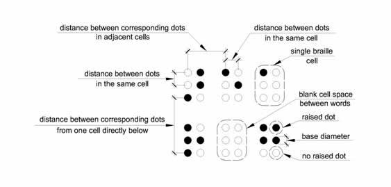
703.3.2 Position. Braille shall be positioned below the corresponding text. If text is multi-lined, braille shall be placed below the entire text. Braille shall be separated 3/8 inch (9.5 mm) minimum from any other tactile characters and 3/8 inch (9.5 mm) minimum from raised borders and decorative elements.
EXCEPTION: Braille provided on elevator car controls shall be separated 3/16 inch (4.8 mm) minimum and shall be located either directly below or adjacent to the corresponding raised characters or symbols.
|
|
|
Figure 703.3.2 Position of Braille |
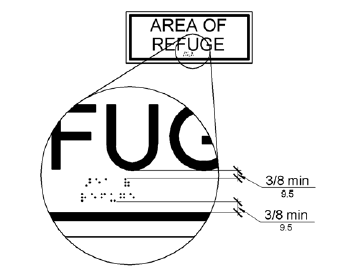
703.4 Installation Height and Location. Signs with tactile characters shall comply with 703.4.
703.4.1 Height above Finish Floor or Ground. Tactile characters on signs shall be located 48 inches (1220 mm) minimum above the finish floor or ground surface, measured from the baseline of the lowest tactile character and 60 inches (1525 mm) maximum above the finish floor or ground surface, measured from the baseline of the highest tactile character.
EXCEPTION: Tactile characters for elevator car controls shall not be required to comply with 703.4.1.
|
|
|
Figure 703.4.1 Height of Tactile Characters above Finish Floor or Ground |
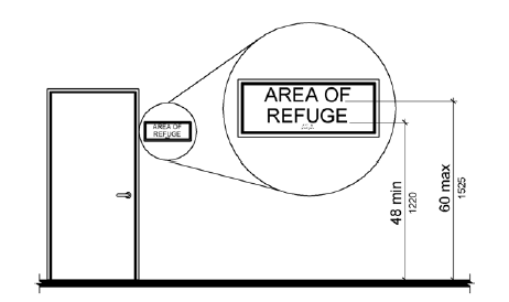
703.4.2 Location. Where a tactile sign is provided at a door, the sign shall be located alongside the door at the latch side. Where a tactile sign is provided at double doors with one active leaf, the sign shall be located on the inactive leaf. Where a tactile sign is provided at double doors with two active leafs, the sign shall be located to the right of the right hand door. Where there is no wall space at the latch side of a single door or at the right side of double doors, signs shall be located on the nearest adjacent wall. Signs containing tactile characters shall be located so that a clear floor space of 18 inches (455 mm) minimum by 18 inches (455 mm) minimum, centered on the tactile characters, is provided beyond the arc of any door swing between the closed position and 45 degree open position.
EXCEPTION: Signs with tactile characters shall be permitted on the push side of doors with closers and without hold-open devices.
|
|
|
Figure 703.4.2 Location of Tactile Signs at Doors |
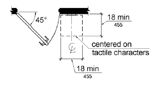
703.5 Visual Characters. Visual characters shall comply with 703.5.
EXCEPTION: Where visual characters comply with 703.2 and are accompanied by braille complying with 703.3, they shall not be required to comply with 703.5.2 through 703.5.9.
703.5.1 Finish and Contrast. Characters and their background shall have a non-glare finish. Characters shall contrast with their background with either light characters on a dark background or dark characters on a light background.
703.5.2 Case. Characters shall be uppercase or lowercase or a combination of both.
703.5.3 Style. Characters shall be conventional in form. Characters shall not be italic, oblique, script, highly decorative, or of other unusual forms.
703.5.4 Character Proportions. Characters shall be selected from fonts where the width of the uppercase letter "O" is 55 percent minimum and 110 percent maximum of the height of the uppercase letter "I".
703.5.5 Character Height. Minimum character height shall comply with Table 703.5.5. Viewing distance shall be measured as the horizontal distance between the character and an obstruction preventing further approach towards the sign. Character height shall be based on the uppercase letter "I".
|
Table 703.5.5 Visual Character Height |
||
|
Height to Finish Floor or Ground From Baseline of Character |
Horizontal Viewing Distance |
Minimum Character Height |
|
40 inches (1015 mm) to less than or equal to 70 inches (1780 mm) |
less than 72 inches (1830 mm) |
5/8 inch (16 mm) |
|
72 inches (1830 mm) and greater |
5/8 inch (16 mm), plus 1/8 inch (3.2 mm) per foot (305 mm) of viewing distance above 72 inches (1830 mm) |
|
|
Greater than 70 inches (1780 mm) to less than or equal to 120 inches (3050 mm) |
less than 180 inches (4570 mm) |
2 inches (51 mm) |
|
180 inches (4570 mm) and greater |
2 inches (51 mm), plus 1/8 inch (3.2 mm) per foot (305 mm) of viewing distance above 180 inches (4570 mm) |
|
|
greater than 120 inches (3050 mm) |
less than 21 feet (6400 mm) |
3 inches (75 mm) |
|
21 feet (6400 mm) and greater |
3 inches (75 mm), plus 1/8 inch (3.2 mm) per foot (305 mm) of viewing distance above 21 feet (6400 mm) |
|
703.5.6 Height from Finish Floor or Ground. Visual characters shall be 40 inches (1015 mm) minimum above the finish floor or ground.
EXCEPTION: Visual characters indicating elevator car controls shall not be required to comply with 703.5.6.
703.5.7 Stroke Thickness. Stroke thickness of the uppercase letter "I" shall be 10 percent minimum and 30 percent maximum of the height of the character.
703.5.8 Character Spacing. Character spacing shall be measured between the two closest points of adjacent characters, excluding word spaces. Spacing between individual characters shall be 10 percent minimum and 35 percent maximum of character height.
703.5.9 Line Spacing. Spacing between the baselines of separate lines of characters within a message shall be 135 percent minimum and 170 percent maximum of the character height.
703.6 Pictograms. Pictograms shall comply with 703.6.
703.6.1 Pictogram Field. Pictograms shall have a field height of 6 inches (150 mm) minimum. Characters and braille shall not be located in the pictogram field.
|
|
|
Figure 703.6.1 Pictogram Field |
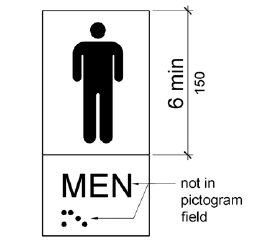
703.6.2 Finish and Contrast. Pictograms and their field shall have a non-glare finish. Pictograms shall contrast with their field with either a light pictogram on a dark field or a dark pictogram on a light field.
703.6.3 Text Descriptors. Pictograms shall have text descriptors located directly below the pictogram field. Text descriptors shall comply with 703.2, 703.3 and 703.4.
703.7 Symbols of Accessibility. Symbols of accessibility shall comply with 703.7.
703.7.1 Finish and Contrast. Symbols of accessibility and their background shall have a non-glare finish. Symbols of accessibility shall contrast with their background with either a light symbol on a dark background or a dark symbol on a light background.
703.7.2 Symbols.
703.7.2.1 International Symbol of Accessibility. The International Symbol of Accessibility shall comply with Figure 703.7.2.1.
|
|
|
Figure 703.7.2.1 International Symbol of Accessibility |
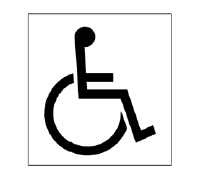
703.7.2.2 International Symbol of TTY. The International Symbol of TTY shall comply with Figure 703.7.2.2.
|
|
|
Figure 703.7.2.2 International Symbol of TTY |

703.7.2.3 Volume Control Telephones. Telephones with a volume control shall be identified by a pictogram of a telephone handset with radiating sound waves on a square field such as shown in Figure 703.7.2.3.
|
|
|
Figure 703.7.2.3 Volume Control Telephone |

703.7.2.4 Assistive Listening Systems. Assistive listening systems shall be identified by the International Symbol of Access for Hearing Loss complying with Figure 703.7.2.4.
|
|
|
Figure 703.7.2.4 International Symbol of Access for Hearing Loss |

704.1 General. Public telephones shall comply with 704.
704.2 Wheelchair Accessible Telephones. Wheelchair accessible telephones shall comply with 704.2.
704.2.1 Clear Floor or Ground Space. A clear floor or ground space complying with 305 shall be provided. The clear floor or ground space shall not be obstructed by bases, enclosures, or seats.
704.2.1.1 Parallel Approach. Where a parallel approach is provided, the distance from the edge of the telephone enclosure to the face of the telephone unit shall be 10 inches (255 mm) maximum.
|
|
|
Figure 704.2.1.1 Parallel Approach to Telephone |
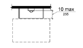
704.2.1.2 Forward Approach. Where a forward approach is provided, the distance from the front edge of a counter within the telephone enclosure to the face of the telephone unit shall be 20 inches (510 mm) maximum.
|
|
|
Figure 704.2.1.2 Forward Approach to Telephone |
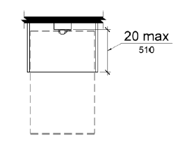
704.2.2 Operable Parts. Operable parts shall comply with 309. Telephones shall have push-button controls where such service is available.
704.2.3 Telephone Directories. Telephone directories, where provided, shall be located in accordance with 309.
704.2.4 Cord Length. The cord from the telephone to the handset shall be 29 inches (735 mm) long minimum.
704.3 Volume Control Telephones. Public telephones required to have volume controls shall be equipped with a receive volume control that provides a gain adjustable up to 20 dB minimum. For incremental volume control, provide at least one intermediate step of 12 dB of gain minimum. An automatic reset shall be provided.
704.4 TTYs. TTYs required at a public pay telephone shall be permanently affixed within, or adjacent to, the telephone enclosure. Where an acoustic coupler is used, the telephone cord shall be sufficiently long to allow connection of the TTY and the telephone receiver.
704.4.1 Height. When in use, the touch surface of TTY keypads shall be 34 inches (865 mm) minimum above the finish floor.
EXCEPTION: Where seats are provided, TTYs shall not be required to comply with 704.4.1.
704.5 TTY Shelf. Public pay telephones required to accommodate portable TTYs shall be equipped with a shelf and an electrical outlet within or adjacent to the telephone enclosure. The telephone handset shall be capable of being placed flush on the surface of the shelf. The shelf shall be capable of accommodating a TTY and shall have 6 inches (150 mm) minimum vertical clearance above the area where the TTY is to be placed.
705.1 General. Detectable warnings shall consist of a surface of truncated domes and shall comply with 705.
705.1.1 Dome Size. Truncated domes in a detectable warning surface shall have a base diameter of 0.9 inch (23 mm) minimum and 1.4 inches (36 mm) maximum, a top diameter of 50 percent of the base diameter minimum to 65 percent of the base diameter maximum, and a height of 0.2 inch (5.1 mm).
705.1.2 Dome Spacing. Truncated domes in a detectable warning surface shall have a center-to-center spacing of 1.6 inches (41 mm) minimum and 2.4 inches (61 mm) maximum, and a base-to-base spacing of 0.65 inch (17 mm) minimum, measured between the most adjacent domes on a square grid.
705.1.3 Contrast. Detectable warning surfaces shall contrast visually with adjacent walking surfaces either light-on-dark, or dark-on-light.
|
|
|
Figure 705.1 Size and Spacing of Truncated Domes |
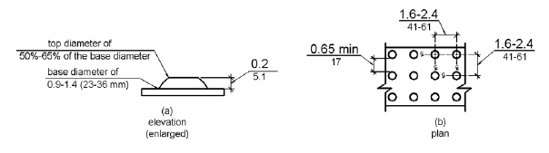
705.2 Platform Edges. Detectable warning surfaces at platform boarding edges shall be 24 inches (610 mm) wide and shall extend the full length of the public use areas of the platform.
706 Assistive Listening Systems
706.1 General. Assistive listening systems required in assembly areas shall comply with 706.
706.2 Receiver Jacks. Receivers required for use with an assistive listening system shall include a 1/8 inch (3.2 mm) standard mono jack.
706.3 Receiver Hearing-Aid Compatibility. Receivers required to be hearing-aid compatible shall interface with telecoils in hearing aids through the provision of neckloops.
706.4 Sound Pressure Level. Assistive listening systems shall be capable of providing a sound pressure level of 110 dB minimum and 118 dB maximum with a dynamic range on the volume control of 50 dB.
706.5 Signal-to-Noise Ratio. The signal-to-noise ratio for internally generated noise in assistive listening systems shall be 18 dB minimum.
706.6 Peak Clipping Level. Peak clipping shall not exceed 18 dB of clipping relative to the peaks of speech.
707 Automatic Teller Machines and Fare Machines
707.1 General. Automatic teller machines and fare machines shall comply with 707.
707.2 Clear Floor or Ground Space. A clear floor or ground space complying with 305 shall be provided.
EXCEPTION: Clear floor or ground space shall not be required at drive-up only automatic teller machines and fare machines.
707.3 Operable Parts. Operable parts shall comply with 309. Unless a clear or correct key is provided, each operable part shall be able to be differentiated by sound or touch, without activation.
EXCEPTION: Drive-up only automatic teller machines and fare machines shall not be required to comply with 309.2 and 309.3.
707.4 Privacy. Automatic teller machines shall provide the opportunity for the same degree of privacy of input and output available to all individuals.
707.5 Speech Output. Machines shall be speech enabled. Operating instructions and orientation, visible transaction prompts, user input verification, error messages, and all displayed information for full use shall be accessible to and independently usable by individuals with vision impairments. Speech shall be delivered through a mechanism that is readily available to all users, including but not limited to, an industry standard connector or a telephone handset. Speech shall be recorded or digitized human, or synthesized.
EXCEPTIONS:
1. Audible tones shall be permitted instead of speech for visible output that is not displayed for security purposes, including but not limited to, asterisks representing personal identification numbers.
2. Advertisements and other similar information shall not be required to be audible unless they convey information that can be used in the transaction being conducted.
3. Where speech synthesis cannot be supported, dynamic alphabetic output shall not be required to be audible.
707.5.1 User Control. Speech shall be capable of being repeated or interrupted. Volume control shall be provided for the speech function.
EXCEPTION: Speech output for any single function shall be permitted to be automatically interrupted when a transaction is selected.
707.5.2 Receipts. Where receipts are provided, speech output devices shall provide audible balance inquiry information, error messages, and all other information on the printed receipt necessary to complete or verify the transaction.
EXCEPTIONS:
1. Machine location, date and time of transaction, customer account number, and the machine identifier shall not be required to be audible.
2. Information on printed receipts that duplicates information available on-screen shall not be required to be presented in the form of an audible receipt.
3. Printed copies of bank statements and checks shall not be required to be audible.
707.6 Input. Input devices shall comply with 707.6.
707.6.1 Input Controls. At least one tactilely discernible input control shall be provided for each function. Where provided, key surfaces not on active areas of display screens, shall be raised above surrounding surfaces. Where membrane keys are the only method of input, each shall be tactilely discernable from surrounding surfaces and adjacent keys.
707.6.2 Numeric Keys. Numeric keys shall be arranged in a 12-key ascending or descending telephone keypad layout. The number five key shall be tactilely distinct from the other keys.
|
|
|
Figure 707.6.2 Numeric Key Layout |
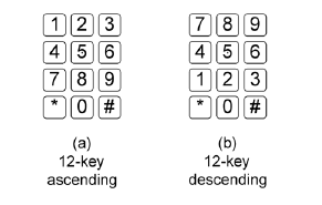
707.6.3 Function Keys. Function keys shall comply with 707.6.3.
707.6.3.1 Contrast. Function keys shall contrast visually from background surfaces. Characters and symbols on key surfaces shall contrast visually from key surfaces. Visual contrast shall be either light-on-dark or dark-on-light.
EXCEPTION: Tactile symbols required by 707.6.3.2 shall not be required to comply with 707.6.3.1.
707.6.3.2 Tactile Symbols. Function key surfaces shall have tactile symbols as follows: Enter or Proceed key: raised circle; Clear or Correct key: raised left arrow; Cancel key: raised letter ex; Add Value key: raised plus sign; Decrease Value key: raised minus sign.
707.7 Display Screen. The display screen shall comply with 707.7.
EXCEPTION: Drive-up only automatic teller machines and fare machines shall not be required to comply with 707.7.1.
707.7.1 Visibility. The display screen shall be visible from a point located 40 inches (1015 mm) above the center of the clear floor space in front of the machine.
707.7.2 Characters. Characters displayed on the screen shall be in a sans serif font. Characters shall be 3/16 inch (4.8 mm) high minimum based on the uppercase letter "I". Characters shall contrast with their background with either light characters on a dark background or dark characters on a light background.
707.8 Braille Instructions. Braille instructions for initiating the speech mode shall be provided. Braille shall comply with 703.3.
708 Two-Way Communication Systems
708.1 General. Two-way communication systems shall comply with 708.
708.2 Audible and Visual Indicators. The system shall provide both audible and visual signals.
708.3 Handsets. Handset cords, if provided, shall be 29 inches (735 mm) long minimum.
708.4 Residential Dwelling Unit Communication Systems. In residential dwelling units required to comply with 809, communications systems between a residential dwelling unit and a site, building, or floor entrance shall comply with 708.4.
708.4.1 Common Use or Public Use System Interface. The common use or public use system interface shall include the capability of supporting voice and TTY communication with the residential dwelling unit interface.
708.4.2 Residential Dwelling Unit Interface. The residential dwelling unit system interface shall include a telephone jack capable of supporting voice and TTY communication with the common use or public use system interface.
CHAPTER 8: SPECIAL ROOMS, SPACES AND ELEMENTS
801.1 Scope. The provisions of Chapter 8 shall apply where required by Chapter 2 or where referenced by a requirement in this document.
802 Wheelchair Spaces, Companion Seats, and Designated Aisle Seats
802.1 Wheelchair Spaces. Wheelchair spaces shall comply with 802.1.
802.1.1 Floor or Ground Surface. The floor or ground surface of wheelchair spaces shall comply with 302. Changes in level are not permitted.
EXCEPTION: Slopes not steeper than 1:48 shall be permitted.
802.1.2 Width. A single wheelchair space shall be 36 inches (915 mm) wide minimum. Where two adjacent wheelchair spaces are provided, each wheelchair space shall be 33 inches (840 mm) wide minimum.
|
|
|
Figure 802.1.2 Width of Wheelchair Spaces in Assembly Areas |
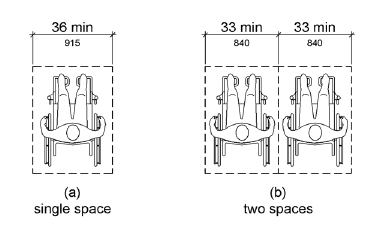
802.1.3 Depth. Where a wheelchair space can be entered from the front or rear, the wheelchair space shall be 48 inches (1220 mm) deep minimum. Where a wheelchair space can be entered only from the side, the wheelchair space shall be 60 inches (1525 mm) deep minimum.
|
|
|
Figure 802.1.3 Depth of Wheelchair Spaces in Assembly Areas |
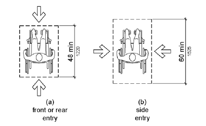
802.1.4 Approach. Wheelchair spaces shall adjoin accessible routes. Accessible routes shall not overlap wheelchair spaces.
802.1.5 Overlap. Wheelchair spaces shall not overlap circulation paths.
802.2 Lines of Sight. Lines of sight to the screen, performance area, or playing field for spectators in wheelchair spaces shall comply with 802.2.
802.2.1 Lines of Sight over Seated Spectators. Where spectators are expected to remain seated during events, spectators in wheelchair spaces shall be afforded lines of sight complying with 802.2.1.
802.2.1.1 Lines of Sight over Heads. Where spectators are provided lines of sight over the heads of spectators seated in the first row in front of their seats, spectators seated in wheelchair spaces shall be afforded lines of sight over the heads of seated spectators in the first row in front of wheelchair spaces.
|
|
|
Figure 802.2.1.1 Lines of Sight over the Heads of Seated Spectators |
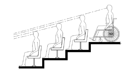
802.2.1.2 Lines of Sight between Heads. Where spectators are provided lines of sight over the shoulders and between the heads of spectators seated in the first row in front of their seats, spectators seated in wheelchair spaces shall be afforded lines of sight over the shoulders and between the heads of seated spectators in the first row in front of wheelchair spaces.
|
|
|
Figure 802.2.1.2 Lines of Sight between the Heads of Seated Spectators |
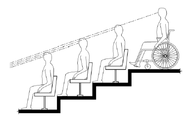
802.2.2 Lines of Sight over Standing Spectators. Where spectators are expected to stand during events, spectators in wheelchair spaces shall be afforded lines of sight complying with 802.2.2.
802.2.2.1 Lines of Sight over Heads. Where standing spectators are provided lines of sight over the heads of spectators standing in the first row in front of their seats, spectators seated in wheelchair spaces shall be afforded lines of sight over the heads of standing spectators in the first row in front of wheelchair spaces.
|
|
|
Figure 802.2.2.1 Lines of Sight over the Heads of Standing Spectators |
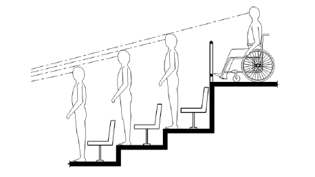
802.2.2.2 Lines of Sight between Heads. Where standing spectators are provided lines of sight over the shoulders and between the heads of spectators standing in the first row in front of their seats, spectators seated in wheelchair spaces shall be afforded lines of sight over the shoulders and between the heads of standing spectators in the first row in front of wheelchair spaces.
|
|
|
Figure 802.2.2.2 Lines of Sight between the Heads of Standing Spectators |
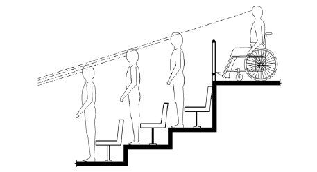
802.3 Companion Seats. Companion seats shall comply with 802.3.
802.3.1 Alignment. In row seating, companion seats shall be located to provide shoulder alignment with adjacent wheelchair spaces. The shoulder alignment point of the wheelchair space shall be measured 36 inches (915 mm) from the front of the wheelchair space. The floor surface of the companion seat shall be at the same elevation as the floor surface of the wheelchair spaces.
802.3.2 Type. Companion seats shall be equivalent in size, quality, comfort, and amenities to the seating in the immediate area. Companion seats shall be permitted to be movable.
802.4 Designated Aisle Seats. Designated aisle seats shall comply with 802.4.
802.4.1 Armrests. Where armrests are provided on the seating in the immediate area, folding or retractable armrests shall be provided on the aisle side of the seat.
802.4.2 Identification. Each designated aisle seat shall be identified by a sign or marker.
803 Dressing, Fitting, and Locker Rooms
803.1 General. Dressing, fitting, and locker rooms shall comply with 803.
803.2 Turning Space. Turning space complying with 304 shall be provided within the room.
803.3 Door Swing. Doors shall not swing into the room unless a clear floor or ground space complying with 305.3 is provided beyond the arc of the door swing.
803.4 Benches. A bench complying with 903 shall be provided within the room.
803.5 Coat Hooks and Shelves. Coat hooks and shelves provided within the room shall be located within one of the reach ranges specified in 308. Shelves shall be 40 inches (1015 mm) minimum and 48 inches (1220 mm) maximum above the finish floor or ground.
803.6 Mirrors. Mirrors provided within the room shall be installed with the bottom edge of the reflecting surface 35 inches (890 mm) maximum above the finish floor or ground.
804.1 General. Kitchens and kitchenettes shall comply with 804.
804.2 Clearance. Where a pass through kitchen is provided, clearances shall comply with 804.2.1. Where a U-shaped kitchen is provided, clearances shall comply with 804.2.2.
EXCEPTION: Spaces that do not provide a cooktop or conventional range shall not be required to comply with 804.2.
804.2.1 Pass-Through Kitchen. In pass through kitchens where counters, appliances or cabinets are on two opposing sides, or where counters, appliances or cabinets are opposite a parallel wall, clearance between all opposing base cabinets, counter tops, appliances, or walls within kitchen work areas shall be 40 inches (1015 mm) minimum. Pass through kitchens shall have two entries.
|
|
|
Figure 804.2.1 Pass-Through Kitchens |
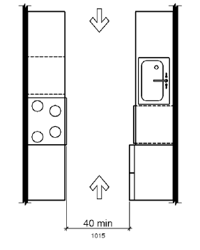
804.2.2 U-Shaped. In U-shaped kitchens enclosed on three contiguous sides, clearance between all opposing base cabinets, counter tops, appliances, or walls within kitchen work areas shall be 60 inches (1525 mm) minimum.
EXCEPTION: In dwelling units in multi-story housing required to comply with 812, where there is no appliance or counter top at the base of the U (see 804.2.2 (b)) and counters provide the knee clearances specified in 306, clearances between those counters and all opposing base cabinets, countertops, appliances, or walls in kitchens shall be 40 inches (1015 mm) minimum.
|
|
|
Figure 804.2.2 U-Shaped Kitchens |
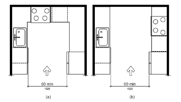
804.3 Kitchen Work Surface. In residential dwelling units required to comply with 809, at least one 30 inches (760 mm) wide minimum section of counter shall provide a kitchen work surface that complies with 804.3.
804.3.1 Clear Floor or Ground Space. A clear floor space complying with 305 positioned for a forward approach shall be provided. The clear floor or ground space shall be centered on the kitchen work surface and shall provide knee and toe clearance complying with 306.
EXCEPTION: Cabinetry shall be permitted under the kitchen work surface provided that all of the following conditions are met:
(a) the cabinetry can be removed without removal or replacement of the kitchen work surface;
(b) the finish floor extends under the cabinetry; and
(c) the walls behind and surrounding the cabinetry are finished.
804.3.2 Height. The kitchen work surface shall be 34 inches (865 mm) maximum above the finish floor or ground.
EXCEPTION: A counter that is adjustable to provide a kitchen work surface at variable heights, 29 inches (735 mm) minimum and 36 inches (915 mm) maximum, shall be permitted.
804.3.3 Exposed Surfaces. There shall be no sharp or abrasive surfaces under the work surface counters.
804.4 Sinks. Sinks shall comply with 606.
804.5 Storage. At least 50 percent of shelf space in storage facilities shall comply with 811.
804.6 Appliances. Where provided, kitchen appliances shall comply with 804.6.
804.6.1 Clear Floor or Ground Space. A clear floor or ground space complying with 305 shall be provided at each kitchen appliance. Clear floor or ground spaces shall be permitted to overlap.
804.6.2 Operable Parts. All appliance controls shall comply with 309.
EXCEPTIONS:
1. Appliance doors and door latching devices shall not be required to comply with 309.4.
2. Bottom-hinged appliance doors, when in the open position, shall not be required to comply with 309.3.
804.6.3 Dishwasher. Clear floor or ground space shall be positioned adjacent to the dishwasher door. The dishwasher door, in the open position, shall not obstruct the clear floor or ground space for the dishwasher or the sink.
804.6.4 Range or Cooktop. Where a forward approach is provided, the clear floor or ground space shall provide knee and toe clearance complying with 306. Where knee and toe space is provided, the underside of the range or cooktop shall be insulated or otherwise configured to prevent burns, abrasions, or electrical shock. The location of controls shall not require reaching across burners.
804.6.5 Oven. Ovens shall comply with 804.6.5.
804.6.5.1 Side-Hinged Door Ovens. Side-hinged door ovens shall have the work surface required by 804.3 positioned adjacent to the latch side of the oven door.
804.6.5.2 Bottom-Hinged Door Ovens. Bottom-hinged door ovens shall have the work surface required by 804.3 positioned adjacent to one side of the door.
804.6.5.3 Controls. Ovens shall have controls on front panels.
804.6.6 Refrigerator/Freezer. Combination refrigerators and freezers shall have at least 50 percent of the freezer space 54 inches (1370 mm) maximum above the finish floor or ground. The clear floor or ground space shall be positioned for a parallel approach to the space dedicated to a refrigerator/freezer with the centerline of the clear floor or ground space offset 24 inches (610 mm) maximum from the centerline of the dedicated space.
805 Medical Care and Long-Term Care Facilities
805.1 General. Medical care facility and long-term care facility patient or resident sleeping rooms required to provide mobility features shall comply with 805.
805.2 Turning Space. Turning space complying with 304 shall be provided within the room.
805.3 Clear Floor or Ground Space. A clear floor space complying with 305 shall be provided on each side of the bed. The clear floor space shall be positioned for parallel approach to the side of the bed.
805.4 Toilet and Bathing Rooms. Toilet and bathing rooms that are provided as part of a patient or resident sleeping room shall comply with 603. Where provided, no fewer than one water closet, one lavatory, and one bathtub or shower shall comply with the applicable requirements of 603 through 610.
806 Transient Lodging Guest Rooms
806.1 General. Transient lodging guest rooms shall comply with 806. Guest rooms required to provide mobility features shall comply with 806.2. Guest rooms required to provide communication features shall comply with 806.3.
806.2 Guest Rooms with Mobility Features. Guest rooms required to provide mobility features shall comply with 806.2.
806.2.1 Living and Dining Areas. Living and dining areas shall be accessible.
806.2.2 Exterior Spaces. Exterior spaces, including patios, terraces and balconies that serve the guest room shall be accessible.
806.2.3 Sleeping Areas. At least one sleeping area shall provide a clear floor space complying with 305 on both sides of a bed. The clear floor space shall be positioned for parallel approach to the side of the bed.
EXCEPTION: Where a single clear floor space complying with 305 positioned for parallel approach is provided between two beds, a clear floor or ground space shall not be required on both sides of a bed.
806.2.4 Toilet and Bathing Facilities. At least one bathroom that is provided as part of a guest room shall comply with 603. No fewer than one water closet, one lavatory, and one bathtub or shower shall comply with applicable requirements of 603 through 610. In addition, required roll-in shower compartments shall comply with 608.2.2 or 608.2.3. Toilet and bathing fixtures required to comply with 603 through 610 shall be permitted to be located in more than one toilet or bathing area, provided that travel between fixtures does not require travel between other parts of the guest room.
806.2.4.1 Vanity Counter Top Space. If vanity counter top space is provided in non-accessible guest toilet or bathing rooms, equivalent vanity counter top space, in terms of size and proximity to the lavatory, shall also be provided in accessible guest toilet or bathing rooms.
806.2.5 Kitchens and Kitchenettes. Kitchens and kitchenettes shall comply with 804.
806.2.6 Turning Space. Turning space complying with 304 shall be provided within the guest room.
806.3 Guest Rooms with Communication Features. Guest rooms required to provide communication features shall comply with 806.3.
806.3.1 Alarms. Where emergency warning systems are provided, alarms complying with 702 shall be provided.
806.3.2 Notification Devices. Visible notification devices shall be provided to alert room occupants of incoming telephone calls and a door knock or bell. Notification devices shall not be connected to visible alarm signal appliances. Telephones shall have volume controls compatible with the telephone system and shall comply with 704.3. Telephones shall be served by an electrical outlet complying with 309 located within 48 inches (1220 mm) of the telephone to facilitate the use of a TTY.
807 Holding Cells and Housing Cells
807.1 General. Holding cells and housing cells shall comply with 807.
807.2 Cells with Mobility Features. Cells required to provide mobility features shall comply with 807.2.
807.2.1 Turning Space. Turning space complying with 304 shall be provided within the cell.
807.2.2 Benches. Where benches are provided, at least one bench shall comply with 903.
807.2.3 Beds. Where beds are provided, clear floor space complying with 305 shall be provided on at least one side of the bed. The clear floor space shall be positioned for parallel approach to the side of the bed.
807.2.4 Toilet and Bathing Facilities. Toilet facilities or bathing facilities that are provided as part of a cell shall comply with 603. Where provided, no fewer than one water closet, one lavatory, and one bathtub or shower shall comply with the applicable requirements of 603 through 610.
807.3 Cells with Communication Features. Cells required to provide communication features shall comply with 807.3.
807.3.1 Alarms. Where audible emergency alarm systems are provided to serve the occupants of cells, visible alarms complying with 702 shall be provided.
EXCEPTION: Visible alarms shall not be required where inmates or detainees are not allowed independent means of egress.
807.3.2 Telephones. Telephones, where provided within cells, shall have volume controls complying with 704.3.
808.1 General. Courtrooms shall comply with 808.
808.2 Turning Space. Where provided, areas that are raised or depressed and accessed by ramps or platform lifts with entry ramps shall provide unobstructed turning space complying with 304.
808.3 Clear Floor Space. Each jury box and witness stand shall have, within its defined area, clear floor space complying with 305.
EXCEPTION: In alterations, wheelchair spaces are not required to be located within the defined area of raised jury boxes or witness stands and shall be permitted to be located outside these spaces where ramp or platform lift access poses a hazard by restricting or projecting into a means of egress required by the appropriate administrative authority.
808.4 Judges' Benches and Courtroom Stations. Judges' benches, clerks' stations, bailiffs' stations, deputy clerks' stations, court reporters' stations, and litigants' and counsel stations shall comply with 902.
809 Residential Dwelling Units
809.1 General. Residential dwelling units required by 233.2, 233.3 and 233.4 shall comply with 809. Residential dwelling units required to provide mobility features shall comply with 809.2 through 809.4. Residential dwelling units required to provide communication features shall comply with 809.5. Dwelling units in multi-story housing required by 233.6 shall comply with 812.
809.2 Accessible Routes. Accessible routes complying with Chapter 4 shall be provided within residential dwelling units in accordance with 809.2.
EXCEPTION: Accessible routes shall not be required to or within unfinished attics or unfinished basements.
809.2.1 Location. At least one accessible route shall connect all spaces and elements which are a part of the residential dwelling units. Where only one accessible route is provided, it shall not pass through bathrooms, closets, or similar spaces.
809.2.2 Turning Space. All rooms served by an accessible route shall provide a turning space complying with 304.
EXCEPTION: Turning space shall not be required in exterior spaces 30 inches (760 mm) maximum in depth or width.
809.3 Kitchen. Where a kitchen is provided, it shall comply with 804.
809.4 Toilet Facilities and Bathing Facilities. At least one bathroom shall comply with 603. No fewer than one of each type of fixture provided shall comply with applicable requirements of 603 through 610. Toilet and bathing fixtures required to comply with 603 through 610 shall be located in the same toilet and bathing area, such that travel between fixtures does not require travel between other parts of the residential dwelling units.
809.5 Residential Dwelling Units with Communication Features. Residential dwelling units required to provide communication features shall comply with 809.5.
809.5.1 Building Fire Alarm System. Where a building fire alarm system is provided, the system wiring shall be extended to a point within the residential dwelling units in the vicinity of the residential dwelling unit smoke detection system.
809.5.1.1 Alarm Appliances. Where alarm appliances are provided within a residential dwelling unit as part of the building fire alarm system, they shall comply with 702.
809.5.1.2 Activation. All visible alarm appliances provided within the residential dwelling unit for building fire alarm notification shall be activated upon activation of the building fire alarm in the portion of the building containing the residential dwelling unit.
809.5.2 Residential Dwelling Unit Smoke Detection System. Residential dwelling unit smoke detection systems shall comply with NFPA 72 (2013 edition) (incorporated by reference, see 105 Referenced Standards in Chapter 1).
809.5.2.1 Activation. All visible alarm appliances provided within the residential dwelling unit for smoke detection notification shall be activated upon smoke detection.
809.5.3 Interconnection. The same visible alarm appliances shall be permitted to provide notification of residential dwelling unit smoke detection and building fire alarm activation.
809.5.4 Prohibited Use. Visible alarm appliances used to indicate residential dwelling unit smoke detection or building fire alarm activation shall not be used for any other purpose within the residential dwelling unit.
809.5.5 Residential Dwelling Unit Primary Entrance. Communication features shall be provided at the residential dwelling unit primary entrance complying with 809.5.5.
809.5.5.1 Notification. A hard-wired electric doorbell shall be provided. A button or switch shall be provided outside the residential dwelling unit primary entrance. Activation of the button or switch shall initiate an audible tone and visible signal within the residential dwelling unit. Where visible doorbell signals are located in sleeping areas, they shall have controls to deactivate the signal.
809.5.5.2 Identification. A means for visually identifying a visitor without opening the residential dwelling unit entry door shall be provided and shall allow for a minimum 180 degree range of view.
809.5.6 Site, Building, or Floor Entrance. Where a system, including a closed-circuit system, permitting voice communication between a visitor and the occupant of the residential dwelling unit is provided, the system shall comply with 708.4.
810.1 General. Transportation facilities shall comply with 810.
810.2 Bus Boarding and Alighting Areas. Bus boarding and alighting areas shall comply with 810.2.
810.2.1 Surface. Bus stop boarding and alighting areas shall have a firm, stable, and slip resistant surface.
810.2.2 Dimensions. Bus stop boarding and alighting areas shall provide a clear length of 96 inches (2440 mm) minimum, measured perpendicular to the curb or vehicle roadway edge, and a clear width of 60 inches (1525 mm) minimum, measured parallel to the vehicle roadway.
|
|
|
Figure 810.2.2 Dimensions of Bus Boarding and Alighting Areas |
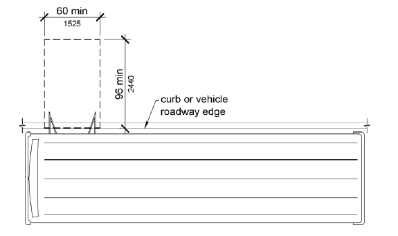
810.2.3 Connection. Bus stop boarding and alighting areas shall be connected to streets, sidewalks, or pedestrian paths by an accessible route complying with 402.
810.2.4 Slope. Parallel to the roadway, the slope of the bus stop boarding and alighting area shall be the same as the roadway, to the maximum extent practicable. Perpendicular to the roadway, the slope of the bus stop boarding and alighting area shall not be steeper than 1:48.
810.3 Bus Shelters. Bus shelters shall provide a minimum clear floor or ground space complying with 305 entirely within the shelter. Bus shelters shall be connected by an accessible route complying with 402 to a boarding and alighting area complying with 810.2. Where seating is provided within transit shelters, the clear space shall be located either at one end of a seat or shall not overlap the area within 18 inches (460 mm) from the front edge of the seat. Environmental controls within transit shelters shall be proximity-actuated. Protruding objects within transit shelters shall comply with 307.
|
|
|
Figure 810.3 Bus Shelters |
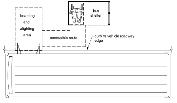
810.4 Bus Signs. Bus route identification signs shall comply with 703.5.1 through 703.5.4, and 703.5.7 and 703.5.8. In addition, to the maximum extent practicable, bus route identification signs shall comply with 703.5.5.
EXCEPTION: Bus schedules, timetables and maps that are posted at the bus stop or bus bay shall not be required to comply.
810.5 Rail Platforms. Rail platforms shall comply with 810.5.
810.5.1 Slope. Rail platforms shall not exceed a slope of 1:48 in all directions.
EXCEPTION: Where platforms serve vehicles operating on existing track or track laid in existing roadway, the slope of the platform parallel to the track shall be permitted to be equal to the slope (grade) of the roadway or existing track.
810.5.2 Detectable Warnings. Detectable warnings complying with 705 shall be provided at the following areas:
1. Platform boarding edges not protected by platform screens or guards shall have detectable warnings complying with 705 along the full length of the public use area of the platform.
2. Pedestrian at-grade rail crossings not located within a street or highway.
3. Boarding and alighting areas at sidewalk or street level transit stops for rail vehicles where the side of the boarding and alighting areas facing the rail vehicles is not protected by screens or guards.
810.5.3 Platform and Vehicle Floor Coordination. Station platforms shall be positioned to coordinate with vehicles in accordance with the applicable requirements of the federal regulation found at 36 CFR 1192. Low-level platforms shall be 8 inches (205 mm) minimum above top of rail. In light rail, commuter rail, and intercity rail systems where it is not operationally or structurally feasible to meet the horizontal gap or vertical difference requirements of part 1192 or 49 CFR 38, mini-high platforms, car-borne or platform-mounted lifts, ramps or bridge plates or similarly manually deployed devices, meeting the requirements of 49 CFR 38, shall suffice.
EXCEPTION: Where vehicles are boarded from sidewalks or street-level, low-level platforms shall be permitted to be less than 8 inches (205 mm).
810.6 Rail Station Signs. Rail station signs shall comply with 810.6.
EXCEPTION. Signs shall not be required to comply with 810.6.1 and 810.6.2 where audible signs are remotely transmitted to hand-held receivers, or are user- or proximity-actuated.
810.6.1 Entrances. Where signs identify a station or its entrance, at least one sign at each entrance shall comply with 703.2 and shall be placed in uniform locations to the maximum extent practicable. Where signs identify a station that has no defined entrance, at least one sign shall comply with 703.2 and shall be placed in a central location.
810.6.2 Routes and Destinations. Lists of stations, routes and destinations served by the station which are located on boarding areas, platforms, or mezzanines shall comply with 703.5. At least one tactile sign identifying the specific station and complying with 703.2 shall be provided on each platform or boarding area. Signs covered by this requirement shall, to the maximum extent practicable, be placed in uniform locations within the system.
EXCEPTION: Where sign space is limited, characters shall not be required to exceed 3 inches (75 mm).
810.6.3 Station Names. Stations covered by this section shall have identification signs complying with 703.5. Signs shall be clearly visible and within the sight lines of standing and sitting passengers from within the vehicle on both sides when not obstructed by another vehicle.
810.7 Public Address Systems. Where public address systems convey audible information to the public, the same or equivalent information shall be provided in a visual format.
810.8 Clocks. Where clocks are provided for use by the public, the clock face shall be uncluttered so that its elements are clearly visible. Hands, numerals and digits shall contrast with the background either light-on-dark or dark-on-light. Where clocks are installed overhead, numerals and digits shall comply with 703.5.
810.9 Escalators. Where provided, escalators shall comply with the sections 6.1.3.5.6 and 6.1.3.6.5 of ASME A17.1 (incorporated by reference, see "Referenced Standards" in Chapter 1) and shall have a clear width of 32 inches (815 mm) minimum.
EXCEPTION: Existing escalators in key stations shall not be required to comply with 810.9.
810.10 Track Crossings. Where a circulation path serving boarding platforms crosses tracks, it shall comply with 402.
EXCEPTION: Openings for wheel flanges shall be permitted to be 2 1/2 inches (64 mm) maximum.
|
|
|
Figure 810.10 (Exception) Track Crossings |
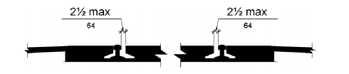
811.1 General. Storage shall comply with 811.
811.2 Clear Floor or Ground Space. A clear floor or ground space complying with 305 shall be provided.
811.3 Height. Storage elements shall comply with at least one of the reach ranges specified in 308.
811.4 Operable Parts. Operable parts shall comply with 309.
812 Dwelling Units in Multi-Story Housing
812.1 General. Dwelling units required by 233.6 in multi-story housing shall comply with 812.
812.2 Adaptability. 812.3 and 812.4 specify a range of heights and clearances within which certain fixtures may be installed (for example, grab bars at bathtubs and water closets, and work surfaces and sink heights in kitchens). In the case of grab bars, provision can be made for later installation within the specified height range, as requested by the occupant of the dwelling unit. Other fixtures may be permanently installed at a height within these ranges, or the fixtures may be adjustable within the ranges. A unit in which fixtures may be added or adjusted in height is an adaptable dwelling unit. Both adaptable dwelling units and units in which fixtures are permanently installed within the heights specified in this section are accessible dwelling units.
812.3 Bathrooms. Bathrooms shall be on an accessible route and shall comply with 812.3.1 through 812.3.5.
812.3.1 Clearances. Clearances shall comply with 603.2.
812.3.2 Water Closets. Water closets shall comply with 604.2 through 604.7.
812.3.3 Lavatories, Mirrors and Medicine Cabinets. If lavatories, mirrors and medicine cabinets are provided, at least one of each shall comply with 812.3.3.1 through 812.3.3.3.
812.3.3.1 Lavatory. The lavatory shall comply with 606.
812.3.3.2 Mirrors. Mirrors shall comply with 603.3.
812.3.3.3 Medicine Cabinet. The medicine cabinet shall have a usable shelf complying with 309.
812.3.4 Bathtubs. Bathtubs shall comply with 607.
812.3.5 Showers. If a shower is provided, a transfer type shower compartment complying with 608.2.1 or a standard roll-in shower compartment complying with 608.2.2 or an alternate roll-in type shower compartment complying with 608.2.3 shall be provided. Showers shall comply with 608.3 through 608.8.
EXCEPTION: A seat, or reinforcement for a seat, shall not be required in the roll-in shower compartment.
812.4 Kitchens. Kitchens and their components shall be on an accessible route and shall comply with 804.2 through 804.4, 804.6.1 through 804.6.4 and 804.6.6.
812.4.1 Kitchen Storage. At least 5%, but not less than one, of each type of cabinet, drawer, and shelf storage area shall comply with 812.4.1.1 through 812.4.1.3.
812.4.2 Ovens shall be of the self-cleaning type or be located adjacent to an adjustable height counter with knee and toe clearance complying with 306. For side-opening ovens, the door latch side shall be next to the open counter space, and there shall be a pull-out shelf under the oven extending the fill width of the oven and pulling out not less than 10 inches (255 mm) when fully extended. Ovens shall have controls on front panels. Oven controls are permitted to be located on either side of the door.
812.4.1.1 Clear Floor Space. A clear floor space complying with 305 shall be provided at each accessible storage area.
812.4.1.2 Height. Accessible storage areas shall be within at least one of the reach ranges specified in 308. At least one shelf of all cabinets and storage shelves mounted above counters shall be mounted at 48 inches (1220 mm) maximum above the floor.
812.4.1.3 Hardware. Hardware for accessible storage facilities shall comply with 309.4. Door pulls or handles for wall cabinets shall be mounted as close to the bottom of cabinet doors as possible. Door pulls or handles for base cabinets shall be mounted as close to the top of cabinet doors as possible.
812.5 Laundry Facilities. Laundry equipment provided within individual accessible dwelling units, and separate laundry facilities that serve one or more accessible dwelling units, shall comply with 611.
CHAPTER 9: BUILT-IN ELEMENTS
901.1 Scope. The provisions of Chapter 9 shall apply where required by Chapter 2 or where referenced by a requirement in this document.
902 Dining Surfaces and Work Surfaces
902.1 General. Dining surfaces and work surfaces shall comply with 902.2 and 902.3.
EXCEPTION: Dining surfaces and work surfaces for children's use shall be permitted to comply with 902.4.
902.2 Clear Floor or Ground Space. A clear floor space complying with 305 positioned for a forward approach shall be provided. Knee and toe clearance complying with 306 shall be provided.
902.3 Height. The tops of dining surfaces and work surfaces shall be 28 inches (710 mm) minimum and 34 inches (865 mm) maximum above the finish floor or ground.
902.4 Dining Surfaces and Work Surfaces for Children's Use. Accessible dining surfaces and work surfaces for children's use shall comply with 902.4.
EXCEPTION: Dining surfaces and work surfaces that are used primarily by children 5 years and younger shall not be required to comply with 902.4 where a clear floor or ground space complying with 305 positioned for a parallel approach is provided.
902.4.1 Clear Floor or Ground Space. A clear floor space complying with 305 positioned for forward approach shall be provided. Knee and toe clearance complying with 306 shall be provided, except that knee clearance 24 inches (610 mm) minimum above the finish floor or ground shall be permitted.
902.4.2 Height. The tops of tables and counters shall be 26 inches (660 mm) minimum and 30 inches (760 mm) maximum above the finish floor or ground.
903.1 General. Benches shall comply with 903.
903.2 Clear Floor or Ground Space. Clear floor or ground space complying with 305 shall be provided and shall be positioned at the end of the bench seat and parallel to the short axis of the bench.
903.3 Size. Benches shall have seats that are 42 inches (1065 mm) long minimum and 20 inches (510 mm) deep minimum and 24 inches (610 mm) deep maximum.
903.4 Back Support. The bench shall provide for back support or shall be affixed to a wall. Back support shall be 42 inches (1065 mm) long minimum and shall extend from a point 2 inches (51 mm) maximum above the seat surface to a point 18 inches (455 mm) minimum above the seat surface. Back support shall be 2 1/2 inches (64 mm) maximum from the rear edge of the seat measured horizontally.
|
|
|
Figure 903.4 Bench Back Support |
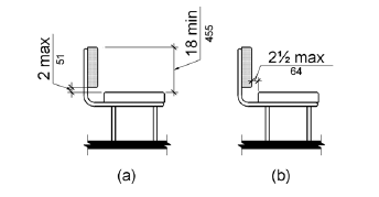
903.5 Height. The top of the bench seat surface shall be 17 inches (430 mm) minimum and 19 inches (485 mm) maximum above the finish floor or ground.
903.6 Structural Strength. Allowable stresses shall not be exceeded for materials used when a vertical or horizontal force of 250 pounds (1112 N) is applied at any point on the seat, fastener, mounting device, or supporting structure.
903.7 Wet Locations. Where installed in wet locations, the surface of the seat shall be slip resistant and shall not accumulate water.
904 Check-Out Aisles and Sales and Service Counters
904.1 General. Check-out aisles and sales and service counters shall comply with the applicable requirements of 904.
904.2 Approach. All portions of counters required to comply with 904 shall be located adjacent to a walking surface complying with 403.
904.3 Check-Out Aisles. Check-out aisles shall comply with 904.3.
904.3.1 Aisle. Aisles shall comply with 403.
904.3.2 Counter. The counter surface height shall be 38 inches (965 mm) maximum above the finish floor or ground. The top of the counter edge protection shall be 2 inches (51 mm) maximum above the top of the counter surface on the aisle side of the check-out counter.
|
|
|
Figure 904.3.2 Check-Out Aisle Counters |
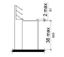
904.3.3 Check Writing Surfaces. Where provided, check writing surfaces shall comply with 902.3.
904.4 Sales and Service Counters. Sales counters and service counters shall comply with 904.4.1 or 904.4.2. The accessible portion of the counter top shall extend the same depth as the sales or service counter top.
EXCEPTION: In alterations, when the provision of a counter complying with 904.4 would result in a reduction of the number of existing counters at work stations or a reduction of the number of existing mail boxes, the counter shall be permitted to have a portion which is 24 inches (610 mm) long minimum complying with 904.4.1 provided that the required clear floor or ground space is centered on the accessible length of the counter.
|
|
|
Figure 904.4 (Exception) Alteration of Sales and Service Counters |
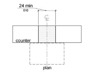
904.4.1 Parallel Approach. A portion of the counter surface that is 36 inches (915 mm) long minimum and 36 inches (915 mm) high maximum above the finish floor shall be provided. A clear floor or ground space complying with 305 shall be positioned for a parallel approach adjacent to the 36 inch (915 mm) minimum length of counter.
EXCEPTION: Where the provided counter surface is less than 36 inches (915 mm) long, the entire counter surface shall be 36 inches (915 mm) high maximum above the finish floor.
904.4.2 Forward Approach. A portion of the counter surface that is 30 inches (760 mm) long minimum and 36 inches (915 mm) high maximum shall be provided. Knee and toe space complying with 306 shall be provided under the counter. A clear floor or ground space complying with 305 shall be positioned for a forward approach to the counter.
904.5 Food Service Lines. Counters in food service lines shall comply with 904.5.
904.5.1 Self-Service Shelves and Dispensing Devices. Self-service shelves and dispensing devices for tableware, dishware, condiments, food and beverages shall comply with 308.
904.5.2 Tray Slides. The tops of tray slides shall be 28 inches (710 mm) minimum and 34 inches (865 mm) maximum above the finish floor or ground.
904.6 Security Glazing. Where counters or teller windows have security glazing to separate personnel from the public, a method to facilitate voice communication shall be provided. Telephone handset devices, if provided, shall comply with 704.3.
CHAPTER 10: RECREATION FACILITIES
1001.1 Scope. The provisions of Chapter 10 shall apply where required by Chapter 2 or where referenced by a requirement in this document.
1002.1 General. Amusement rides shall comply with 1002.
1002.2 Accessible Routes. Accessible routes serving amusement rides shall comply with Chapter 4.
EXCEPTIONS:
1. In load or unload areas and on amusement rides, where compliance with 405.2 is not structurally or operationally feasible, ramp slope shall be permitted to be 1:8 maximum.
2. In load or unload areas and on amusement rides, handrails provided along walking surfaces complying with 403 and required on ramps complying with 405 shall not be required to comply with 505 where compliance is not structurally or operationally feasible.
1002.3 Load and Unload Areas. A turning space complying with 304.2 and 304.3 shall be provided in load and unload areas.
1002.4 Wheelchair Spaces in Amusement Rides. Wheelchair spaces in amusement rides shall comply with 1002.4.
1002.4.1 Floor or Ground Surface. The floor or ground surface of wheelchair spaces shall be stable and firm.
1002.4.2 Slope. The floor or ground surface of wheelchair spaces shall have a slope not steeper than 1:48 when in the load and unload position.
1002.4.3 Gaps. Floors of amusement rides with wheelchair spaces and floors of load and unload areas shall be coordinated so that, when amusement rides are at rest in the load and unload position, the vertical difference between the floors shall be within plus or minus 5/8 inches (16 mm) and the horizontal gap shall be 3 inches (75 mm) maximum under normal passenger load conditions.
EXCEPTION: Where compliance is not operationally or structurally feasible, ramps, bridge plates, or similar devices complying with the applicable requirements of 36 CFR 1192.83(c) shall be provided.
1002.4.4 Clearances. Clearances for wheelchair spaces shall comply with 1002.4.4.
EXCEPTIONS:
1. Where provided, securement devices shall be permitted to overlap required clearances.
2. Wheelchair spaces shall be permitted to be mechanically or manually repositioned.
3. Wheelchair spaces shall not be required to comply with 307.4.
1002.4.4.1 Width and Length. Wheelchair spaces shall provide a clear width of 30 inches (760 mm) minimum and a clear length of 48 inches (1220 mm) minimum measured to 9 inches (230 mm) minimum above the floor surface.
1002.4.4.2 Side Entry. Where wheelchair spaces are entered only from the side, amusement rides shall be designed to permit sufficient maneuvering clearance for individuals using a wheelchair or mobility aid to enter and exit the ride.
1002.4.4.3 Permitted Protrusions in Wheelchair Spaces. Objects are permitted to protrude a distance of 6 inches (150 mm) maximum along the front of the wheelchair space, where located 9 inches (230 mm) minimum and 27 inches (685 mm) maximum above the floor or ground surface of the wheelchair space. Objects are permitted to protrude a distance of 25 inches (635 mm) maximum along the front of the wheelchair space, where located more than 27 inches (685 mm) above the floor or ground surface of the wheelchair space.
|
|
|
Figure 1002.4.4.3 Protrusions in Wheelchair Spaces in Amusement Rides |
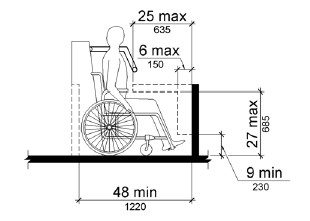
1002.4.5 Ride Entry. Openings providing entry to wheelchair spaces on amusement rides shall be 32 inches (815 mm) minimum clear.
1002.4.6 Approach. One side of the wheelchair space shall adjoin an accessible route when in the load and unload position.
1002.4.7 Companion Seats. Where the interior width of the amusement ride is greater than 53 inches (1345 mm), seating is provided for more than one rider, and the wheelchair is not required to be centered within the amusement ride, a companion seat shall be provided for each wheelchair space.
1002.4.7.1 Shoulder-to-Shoulder Seating. Where an amusement ride provides shoulder-to-shoulder seating, companion seats shall be shoulder-to-shoulder with the adjacent wheelchair spaces.
EXCEPTION: Where shoulder-to-shoulder companion seating is not operationally or structurally feasible, compliance with this requirement shall be required to the maximum extent practicable.
1002.5 Amusement Ride Seats Designed for Transfer. Amusement ride seats designed for transfer shall comply with 1002.5 when positioned for loading and unloading.
1002.5.1 Clear Floor or Ground Space. A clear floor or ground space complying with 305 shall be provided in the load and unload area adjacent to the amusement ride seats designed for transfer.
1002.5.2 Transfer Height. The height of amusement ride seats designed for transfer shall be 14 inches (355 mm) minimum and 24 inches (610 mm) maximum measured from the surface of the load and unload area.
1002.5.3 Transfer Entry. Where openings are provided for transfer to amusement ride seats, the openings shall provide clearance for transfer from a wheelchair or mobility aid to the amusement ride seats.
1002.5.4 Wheelchair Storage Space. Wheelchair storage spaces complying with 305 shall be provided in or adjacent to unload areas for each required amusement ride seats designed for transfer and shall not overlap any required means of egress or accessible route.
1002.6 Transfer Devices for Use with Amusement Rides. Transfer devices for use with amusement rides shall comply with 1002.6 when positioned for loading and unloading.
1002.6.1 Clear Floor or Ground Space. A clear floor or ground space complying with 305 shall be provided in the load and unload area adjacent to the transfer device.
1002.6.2 Transfer Height. The height of transfer device seats shall be 14 inches (355 mm) minimum and 24 inches (610 mm) maximum measured from the load and unload surface.
1002.6.3 Wheelchair Storage Space. Wheelchair storage spaces complying with 305 shall be provided in or adjacent to unload areas for each required transfer device and shall not overlap any required means of egress or accessible route.
1003 Recreational Boating Facilities
1003.1 General. Recreational boating facilities shall comply with 1003.
1003.2 Accessible Routes. Accessible routes serving recreational boating facilities, including gangways and floating piers, shall comply with Chapter 4 except as modified by the exceptions in 1003.2.
1003.2.1 Boat Slips. Accessible routes serving boat slips shall be permitted to use the exceptions in 1003.2.1.
EXCEPTIONS:
1. Where an existing gangway or series of gangways is replaced or altered, an increase in the length of the gangway shall not be required to comply with 1003.2 unless required by 202.4.
2. Gangways shall not be required to comply with the maximum rise specified in 405.6.
3. Where the total length of a gangway or series of gangways serving as part of a required accessible route is 80 feet (24 m) minimum, gangways shall not be required to comply with 405.2.
4. Where facilities contain fewer than 25 boat slips and the total length of the gangway or series of gangways serving as part of a required accessible route is 30 feet (9145 mm) minimum, gangways shall not be required to comply with 405.2.
5. Where gangways connect to transition plates, landings specified by 405.7 shall not be required.
6. Where gangways and transition plates connect and are required to have handrails, handrail extensions shall not be required. Where handrail extensions are provided on gangways or transition plates, the handrail extensions shall not be required to be parallel with the ground or floor surface.
7. The cross slope specified in 403.3 and 405.3 for gangways, transition plates, and floating piers that are part of accessible routes shall be measured in the static position.
8. Changes in level complying with 303.3 and 303.4 shall be permitted on the surfaces of gangways and boat launch ramps.
1003.2.2 Boarding Piers at Boat Launch Ramps. Accessible routes serving boarding piers at boat launch ramps shall be permitted to use the exceptions in 1003.2.2.
EXCEPTIONS:
1. Accessible routes serving floating boarding piers shall be permitted to use Exceptions 1, 2, 5, 6, 7 and 8 in 1003.2.1.
2. Where the total length of the gangway or series of gangways serving as part of a required accessible route is 30 feet (9145 mm) minimum, gangways shall not be required to comply with 405.2.
3. Where the accessible route serving a floating boarding pier or skid pier is located within a boat launch ramp, the portion of the accessible route located within the boat launch ramp shall not be required to comply with 405.
1003.3 Clearances. Clearances at boat slips and on boarding piers at boat launch ramps shall comply with 1003.3.
1003.3.1 Boat Slip Clearance. Boat slips shall provide clear pier space 60 inches (1525 mm) wide minimum and at least as long as the boat slips. Each 10 feet (3050 mm) maximum of linear pier edge serving boat slips shall contain at least one continuous clear opening 60 inches (1525 mm) wide minimum.
EXCEPTIONS:
1. Clear pier space shall be permitted to be 36 inches (915 mm) wide minimum for a length of 24 inches (610 mm) maximum, provided that multiple 36 inch (915 mm) wide segments are separated by segments that are 60 inches (1525 mm) wide minimum and 60 inches (1525 mm) long minimum.
2. Edge protection shall be permitted at the continuous clear openings, provided that it is 4 inches (100 mm) high maximum and 2 inches (51 mm) wide maximum.
3. In existing piers, clear pier space shall be permitted to be located perpendicular to the boat slip and shall extend the width of the boat slip, where the facility has at least one boat slip complying with 1003.3, and further compliance with 1003.3 would result in a reduction in the number of boat slips available or result in a reduction of the widths of existing slips.
|
|
|
Figure 1003.3.1 Boat Slip Clearance |
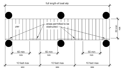
|
|
|
Figure 1003.3.1 (Exception 1) Clear Pier Space Reduction at Boat Slips |
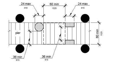
|
|
|
Figure 1003.3.1 (Exception 2) Edge Protection at Boat Slips |
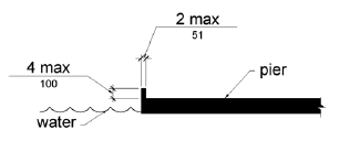
1003.3.2 Boarding Pier Clearances. Boarding piers at boat launch ramps shall provide clear pier space 60 inches (1525 mm) wide minimum and shall extend the full length of the boarding pier. Every 10 feet (3050 mm) maximum of linear pier edge shall contain at least one continuous clear opening 60 inches (1525 mm) wide minimum.
EXCEPTIONS:
1. The clear pier space shall be permitted to be 36 inches (915 mm) wide minimum for a length of 24 inches (610 mm) maximum provided that multiple 36 inch (915 mm) wide segments are separated by segments that are 60 inches (1525 mm) wide minimum and 60 inches (1525 mm) long minimum.
2. Edge protection shall be permitted at the continuous clear openings provided that it is 4 inches (100 mm) high maximum and 2 inches (51 mm) wide maximum.
|
|
|
Figure 1003.3.2 Boarding Pier Clearance |
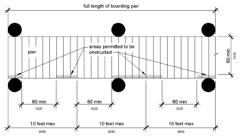
|
|
|
Figure 1003.3.2 (Exception 1) Clear Pier Space Reduction at Boarding Piers |
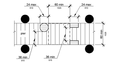
|
|
|
Figure 1003.3.2 (Exception 2) Edge Protection at Boarding Piers |
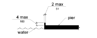
1004 Exercise Machines and Equipment
1004.1 Clear Floor Space. Exercise machines and equipment shall have a clear floor space complying with 305 positioned for transfer or for use by an individual seated in a wheelchair. Clear floor or ground spaces required at exercise machines and equipment shall be permitted to overlap.
1005 Fishing Piers and Platforms
1005.1 Accessible Routes. Accessible routes serving fishing piers and platforms, including gangways and floating piers, shall comply with Chapter 4.
EXCEPTIONS:
1. Accessible routes serving floating fishing piers and platforms shall be permitted to use Exceptions 1, 2, 5, 6, 7 and 8 in 1003.2.1.
2. Where the total length of the gangway or series of gangways serving as part of a required accessible route is 30 feet (9145 mm) minimum, gangways shall not be required to comply with 405.2.
1005.2 Railings. Where provided, railings, guards, or handrails shall comply with 1005.2.
1005.2.1 Height. At least 25 percent of the railings, guards, or handrails shall be 34 inches (865 mm) maximum above the ground or deck surface.
EXCEPTION: Where a guard complying with sections 1015.3, 1015.4 and 1608.7 of the International Building Code (2015 edition) (incorporated by reference, see "Referenced Standards" in Chapter 1) is provided, the guard shall not be required to comply with 1005.2.1.
1005.2.1.1 Dispersion. Railings, guards, or handrails required to comply with 1005.2.1 shall be dispersed throughout the fishing pier or platform.
1005.3 Edge Protection. Where railings, guards, or handrails complying with 1005.2 are provided, edge protection complying with 1005.3.1 or 1005.3.2 shall be provided.
1005.3.1 Curb or Barrier. Curbs or barriers shall extend 2 inches (51 mm) minimum above the surface of the fishing pier or platform.
1005.3.2 Extended Ground or Deck Surface. The ground or deck surface shall extend 12 inches (305 mm) minimum beyond the inside face of the railing. Toe clearance shall be provided and shall be 30 inches (760 mm) wide minimum and 9 inches (230 mm) minimum above the ground or deck surface beyond the railing.
|
|
|
Figure 1005.3.2 Extended Ground or Deck Surface at Fishing Piers and Platforms |
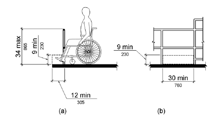
1005.4 Clear Floor or Ground Space. At each location where there are railings, guards, or handrails complying with 1005.2.1, a clear floor or ground space complying with 305 shall be provided. Where there are no railings, guards, or handrails, at least one clear floor or ground space complying with 305 shall be provided on the fishing pier or platform.
1005.5 Turning Space. At least one turning space complying with 304.3 shall be provided on fishing piers and platforms.
1006.1 General. Golf facilities shall comply with 1006.
1006.2 Accessible Routes. Accessible routes serving teeing grounds, practice teeing grounds, putting greens, practice putting greens, teeing stations at driving ranges, course weather shelters, golf car rental areas, bag drop areas, and course toilet rooms shall comply with Chapter 4 and shall be 48 inches (1220 mm) wide minimum. Where handrails are provided, accessible routes shall be 60 inches (1525 mm) wide minimum.
EXCEPTION: Handrails shall not be required on golf courses. Where handrails are provided on golf courses, the handrails shall not be required to comply with 505.
1006.3 Golf Car Passages. Golf car passages shall comply with 1006.3.
1006.3.1 Clear Width. The clear width of golf car passages shall be 48 inches (1220 mm) minimum.
1006.3.2 Barriers. Where curbs or other constructed barriers prevent golf cars from entering a fairway, openings 60 inches (1525 mm) wide minimum shall be provided at intervals not to exceed 75 yards (69 m).
1006.4 Weather Shelters. A clear floor or ground space 60 inches (1525 mm) minimum by 96 inches (2440 mm) minimum shall be provided within weather shelters.
1007 Miniature Golf Facilities
1007.1 General. Miniature golf facilities shall comply with 1007.
1007.2 Accessible Routes. Accessible routes serving holes on miniature golf courses shall comply with Chapter 4. Accessible routes located on playing surfaces of miniature golf holes shall be permitted to use the exceptions in 1007.2.
EXCEPTIONS:
1. Playing surfaces shall not be required to comply with 302.2.
2. Where accessible routes intersect playing surfaces of holes, a 1 inch (25 mm) maximum curb shall be permitted for a width of 32 inches (815 mm) minimum.
3. A slope not steeper than 1:4 for a 4 inch (100 mm) maximum rise shall be permitted.
4. Ramp landing slopes specified by 405.7.1 shall be permitted to be 1:20 maximum.
5. Ramp landing length specified by 405.7.3 shall be permitted to be 48 inches (1220 mm) long minimum.
6. Ramp landing size specified by 405.7.4 shall be permitted to be 48 inches (1220 mm) minimum by 60 inches (1525 mm) minimum.
7. Handrails shall not be required on holes. Where handrails are provided on holes, the handrails shall not be required to comply with 505.
1007.3 Miniature Golf Holes. Miniature golf holes shall comply with 1007.3.
1007.3.1 Start of Play. A clear floor or ground space 48 inches (1220 mm) minimum by 60 inches (1525 mm) minimum with slopes not steeper than 1:48 shall be provided at the start of play.
1007.3.2 Golf Club Reach Range Area. All areas within holes where golf balls rest shall be within 36 inches (915 mm) maximum of a clear floor or ground space 36 inches (915 mm) wide minimum and 48 inches (1220 mm) long minimum having a running slope not steeper than 1:20. The clear floor or ground space shall be served by an accessible route.
|
|
|
Figure 1007.3.2 Golf Club Reach Range Area |
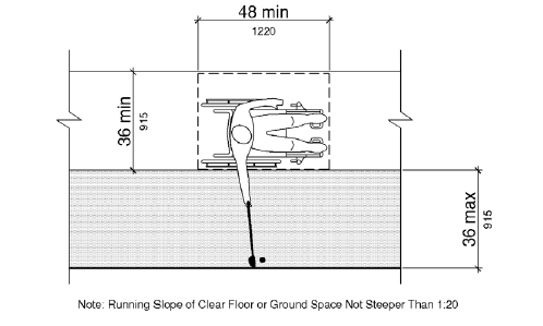
1008.1 General. Play areas shall comply with 1008.
1008.2 Accessible Routes. Accessible routes serving play areas shall comply with Chapter 4 and 1008.2 and shall be permitted to use the exceptions in 1008.2.1 through 1008.2.3. Where accessible routes serve ground level play components, the vertical clearance shall be 80 inches high (2030 mm) minimum.
1008.2.1 Ground Level and Elevated Play Components. Accessible routes serving ground level play components and elevated play components shall be permitted to use the exceptions in 1008.2.1.
EXCEPTIONS:
1. Transfer systems complying with 1008.3 shall be permitted to connect elevated play components except where 20 or more elevated play components are provided no more than 25 percent of the elevated play components shall be permitted to be connected by transfer systems.
2. Where transfer systems are provided, an elevated play component shall be permitted to connect to another elevated play component as part of an accessible route.
1008.2.2 Soft Contained Play Structures. Accessible routes serving soft contained play structures shall be permitted to use the exception in 1008.2.2.
EXCEPTION: Transfer systems complying with 1008.3 shall be permitted to be used as part of an accessible route.
1008.2.3 Water Play Components. Accessible routes serving water play components shall be permitted to use the exceptions in 1008.2.3.
EXCEPTIONS:
1. Where the surface of the accessible route, clear floor or ground spaces, or turning spaces serving water play components is submerged, compliance with 302, 403.3, 405.2, 405.3, and 1008.2.6 shall not be required.
2. Transfer systems complying with 1008.3 shall be permitted to connect elevated play components in water.
1008.2.4 Clear Width. Accessible routes connecting play components shall provide a clear width complying with 1008.2.4.
1008.2.4.1 Ground Level. At ground level, the clear width of accessible routes shall be 60 inches (1525 mm) minimum.
EXCEPTIONS:
1. In play areas less than 1000 square feet (93 m2), the clear width of accessible routes shall be permitted to be 44 inches (1120 mm) minimum, if at least one turning space complying with 304.3 is provided where the restricted accessible route exceeds 30 feet (9145 mm) in length.
2. The clear width of accessible routes shall be permitted to be 36 inches (915 mm) minimum for a distance of 60 inches (1525 mm) maximum provided that multiple reduced width segments are separated by segments that are 60 inches (1525 mm) wide minimum and 60 inches (1525 mm) long minimum.
1008.2.4.2 Elevated. The clear width of accessible routes connecting elevated play components shall be 36 inches (915 mm) minimum.
EXCEPTIONS:
1. The clear width of accessible routes connecting elevated play components shall be permitted to be reduced to 32 inches (815 mm) minimum for a distance of 24 inches (610 mm) maximum provided that reduced width segments are separated by segments that are 48 inches (1220 mm) long minimum and 36 inches (915 mm) wide minimum.
2. The clear width of transfer systems connecting elevated play components shall be permitted to be 24 inches (610 mm) minimum.
1008.2.5 Ramps. Within play areas, ramps connecting ground level play components and ramps connecting elevated play components shall comply with 1008.2.5.
1008.2.5.1 Ground Level. Ramp runs connecting ground level play components shall have a running slope not steeper than 1:16.
1008.2.5.2 Elevated. The rise for any ramp run connecting elevated play components shall be 12 inches (305 mm) maximum.
1008.2.5.3 Handrails. Where required on ramps serving play components, the handrails shall comply with 505 except as modified by 1008.2.5.3.
EXCEPTIONS:
1. Handrails shall not be required on ramps located within ground level use zones.
2. Handrail extensions shall not be required.
1008.2.5.3.1 Handrail Gripping Surfaces. Handrail gripping surfaces with a circular cross section shall have an outside diameter of 0.95 inch (24 mm) minimum and 1.55 inches (39 mm) maximum. Where the shape of the gripping surface is non-circular, the handrail shall provide an equivalent gripping surface.
1008.2.5.3.2 Handrail Height. The top of handrail gripping surfaces shall be 20 inches (510 mm) minimum and 28 inches (710 mm) maximum above the ramp surface.
1008.2.6 Ground Surfaces. Ground surfaces on accessible routes, clear floor or ground spaces, and turning spaces shall comply with 1008.2.6.
1008.2.6.1 Accessibility. Ground surfaces shall comply with ASTM F 1951 (incorporated by reference, see "Referenced Standards" in Chapter 1). Ground surfaces shall be inspected and maintained regularly and frequently to ensure continued compliance with ASTM F 1951.
1008.2.6.2 Use Zones. Ground surfaces located within use zones shall comply with ASTM F 1292 (1999 edition or 2004 edition) (incorporated by reference, see "Referenced Standards" in Chapter 1).
1008.3 Transfer Systems. Where transfer systems are provided to connect to elevated play components, transfer systems shall comply with 1008.3.
1008.3.1 Transfer Platforms. Transfer platforms shall be provided where transfer is intended from wheelchairs or other mobility aids. Transfer platforms shall comply with 1008.3.1.
1008.3.1.1 Size. Transfer platforms shall have level surfaces 14 inches (355 mm) deep minimum and 24 inches (610 mm) wide minimum.
1008.3.1.2 Height. The height of transfer platforms shall be 11 inches (280 mm) minimum and 18 inches (455 mm) maximum measured to the top of the surface from the ground or floor surface.
1008.3.1.3 Transfer Space. A transfer space complying with 305.2 and 305.3 shall be provided adjacent to the transfer platform. The 48 inch (1220 mm) long minimum dimension of the transfer space shall be centered on and parallel to the 24 inch (610 mm) long minimum side of the transfer platform. The side of the transfer platform serving the transfer space shall be unobstructed.
1008.3.1.4 Transfer Supports. At least one means of support for transferring shall be provided.
|
|
|
Figure 1008.3.1 Transfer Platforms |
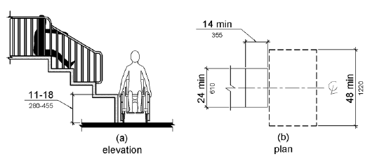
1008.3.2 Transfer Steps. Transfer steps shall be provided where movement is intended from transfer platforms to levels with elevated play components required to be on accessible routes. Transfer steps shall comply with 1008.3.2.
1008.3.2.1 Size. Transfer steps shall have level surfaces 14 inches (355 mm) deep minimum and 24 inches (610 mm) wide minimum.
1008.3.2.2 Height. Each transfer step shall be 8 inches (205 mm) high maximum.
1008.3.2.3 Transfer Supports. At least one means of support for transferring shall be provided.
|
|
|
Figure 1008.3.2 Transfer Steps |
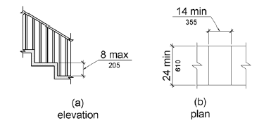
1008.4 Play Components. Ground level play components on accessible routes and elevated play components connected by ramps shall comply with 1008.4.
1008.4.1 Turning Space. At least one turning space complying with 304 shall be provided on the same level as play components. Where swings are provided, the turning space shall be located immediately adjacent to the swing.
1008.4.2 Clear Floor or Ground Space. Clear floor or ground space complying with 305.2 and 305.3 shall be provided at play components.
1008.4.3 Play Tables. Where play tables are provided, knee clearance 24 inches (610 mm) high minimum, 17 inches deep (430 mm) minimum, and 30 inches (760 mm) wide minimum shall be provided. The tops of rims, curbs, or other obstructions shall be 31 inches (785 mm) high maximum.
EXCEPTION: Play tables designed and constructed primarily for children 5 years and younger shall not be required to provide knee clearance where the clear floor or ground space required by 1008.4.2 is arranged for a parallel approach.
1008.4.4 Entry Points and Seats. Where play components require transfer to entry points or seats, the entry points or seats shall be 11 inches (280 mm) minimum and 24 inches (610 mm) maximum from the clear floor or ground space.
EXCEPTION: Entry points of slides shall not be required to comply with 1008.4.4.
1008.4.5 Transfer Supports. Where play components require transfer to entry points or seats, at least one means of support for transferring shall be provided.
1009 Swimming Pools, Wading Pools, and Spas
1009.1 General. Where provided, pool lifts, sloped entries, transfer walls, transfer systems, and pool stairs shall comply with 1009.
1009.2 Pool Lifts. Pool lifts shall comply with 1009.2.
1009.2.1 Pool Lift Location. Pool lifts shall be located where the water level does not exceed 48 inches (1220 mm).
EXCEPTIONS:
1. Where the entire pool depth is greater than 48 inches (1220 mm), compliance with 1009.2.1 shall not be required.
2. Where multiple pool lift locations are provided, no more than one pool lift shall be required to be located in an area where the water level is 48 inches (1220 mm) maximum.
1009.2.2 Seat Location. In the raised position, the centerline of the seat shall be located over the deck and 16 inches (405 mm) minimum from the edge of the pool. The deck surface between the centerline of the seat and the pool edge shall have a slope not steeper than 1:48.
|
|
|
Figure 1009.2.2 Pool Lift Seat Location |
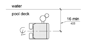
1009.2.3 Clear Deck Space. On the side of the seat opposite the water, a clear deck space shall be provided parallel with the seat. The space shall be 36 inches (915 mm) wide minimum and shall extend forward 48 inches (1220 mm) minimum from a line located 12 inches (305 mm) behind the rear edge of the seat. The clear deck space shall have a slope not steeper than 1:48.
|
|
|
Figure 1009.2.3 Clear Deck Space at Pool Lifts |
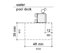
1009.2.4 Seat Height. The height of the lift seat shall be designed to allow a stop at 16 inches (405 mm) minimum to 19 inches (485 mm) maximum measured from the deck to the top of the seat surface when in the raised (load) position.
|
|
|
Figure 1009.2.4 Pool Lift Seat Height |
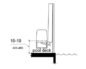
1009.2.5 Seat Width. The seat shall be 16 inches (405 mm) wide minimum.
1009.2.6 Footrests and Armrests. Footrests shall be provided and shall move with the seat. If provided, the armrest positioned opposite the water shall be removable or shall fold clear of the seat when the seat is in the raised (load) position.
EXCEPTION: Footrests shall not be required on pool lifts provided in spas.
1009.2.7 Operation. The lift shall be capable of unassisted operation from both the deck and water levels. Controls and operating mechanisms shall be unobstructed when the lift is in use and shall comply with 309.4.
1009.2.8 Submerged Depth. The lift shall be designed so that the seat will submerge to a water depth of 18 inches (455 mm) minimum below the stationary water level.
|
|
|
Figure 1009.2.8 Pool Lift Submerged Depth |
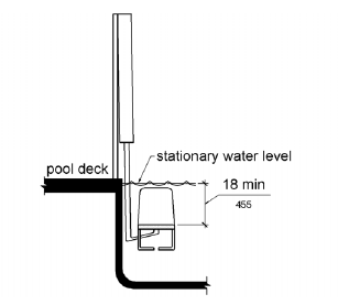
1009.2.9 Lifting Capacity. Single person pool lifts shall have a weight capacity of 300 pounds. (136 kg) minimum and be capable of sustaining a static load of at least one and a half times the rated load.
1009.3 Sloped Entries. Sloped entries shall comply with 1009.3.
1009.3.1 Sloped Entries. Sloped entries shall comply with Chapter 4 except as modified in 1009.3.1 through 1009.3.3.
EXCEPTION: Where sloped entries are provided, the surfaces shall not be required to be slip resistant.
1009.3.2 Submerged Depth. Sloped entries shall extend to a depth of 24 inches (610 mm) minimum and 30 inches (760 mm) maximum below the stationary water level. Where landings are required by 405.7, at least one landing shall be located 24 inches (610 mm) minimum and 30 inches (760 mm) maximum below the stationary water level.
EXCEPTION: In wading pools, the sloped entry and landings, if provided, shall extend to the deepest part of the wading pool.
|
|
|
Figure 1009.3.2 Sloped Entry Submerged Depth |
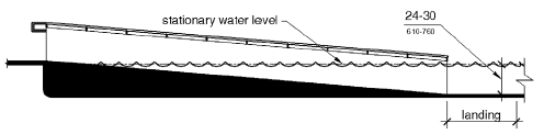
1009.3.3 Handrails. At least two handrails complying with 505 shall be provided on the sloped entry. The clear width between required handrails shall be 33 inches (840 mm) minimum and 38 inches (965 mm) maximum.
EXCEPTIONS:
1. Handrail extensions specified by 505.10.1 shall not be required at the bottom landing serving a sloped entry .
2. Where a sloped entry is provided for wave action pools, leisure rivers, sand bottom pools, and other pools where user access is limited to one area, the handrails shall not be required to comply with the clear width requirements of 1009.3.3.
3. Sloped entries in wading pools shall not be required to provide handrails complying with 1009.3.3. If provided, handrails on sloped entries in wading pools shall not be required to comply with 505.
|
|
|
Figure 1009.3.3 Handrails for Sloped Entry |
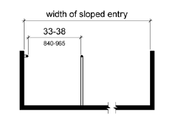
1009.4 Transfer Walls. Transfer walls shall comply with 1009.4.
1009.4.1 Clear Deck Space. A clear deck space of 60 inches (1525 mm) minimum by 60 inches (1525 mm) minimum with a slope not steeper than 1:48 shall be provided at the base of the transfer wall. Where one grab bar is provided, the clear deck space shall be centered on the grab bar. Where two grab bars are provided, the clear deck space shall be centered on the clearance between the grab bars.
|
|
|
Figure 1009.4.1 Clear Deck Space at Transfer Walls |
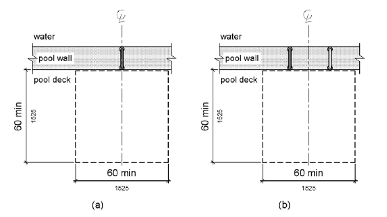
1009.4.2 Height. The height of the transfer wall shall be 16 inches (405 mm) minimum and 19 inches (485 mm) maximum measured from the deck.
|
|
|
Figure 1009.4.2 Transfer Wall Height |
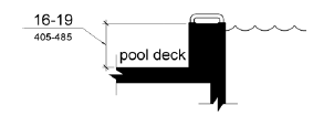
1009.4.3 Wall Depth and Length. The depth of the transfer wall shall be 12 inches (305 mm) minimum and 16 inches (405 mm) maximum. The length of the transfer wall shall be 60 inches (1525 mm) minimum and shall be centered on the clear deck space.
|
|
|
Figure 1009.4.3 Depth and Length of Transfer Walls |
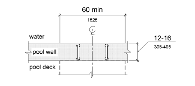
1009.4.4 Surface. Surfaces of transfer walls shall not be sharp and shall have rounded edges.
1009.4.5 Grab Bars. At least one grab bar complying with 609 shall be provided on the transfer wall. Grab bars shall be perpendicular to the pool wall and shall extend the full depth of the transfer wall. The top of the gripping surface shall be 4 inches (100 mm) minimum and 6 inches (150 mm) maximum above transfer walls. Where one grab bar is provided, clearance shall be 24 inches (610 mm) minimum on both sides of the grab bar. Where two grab bars are provided, clearance between grab bars shall be 24 inches (610 mm) minimum.
EXCEPTION: Grab bars on transfer walls shall not be required to comply with 609.4.
|
|
|
Figure 1009.4.5 Grab Bars for Transfer Walls |
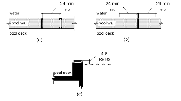
1009.5 Transfer Systems. Transfer systems shall comply with 1009.5.
1009.5.1 Transfer Platform. A transfer platform shall be provided at the head of each transfer system. Transfer platforms shall provide 19 inches (485 mm) minimum clear depth and 24 inches (610 mm) minimum clear width.
|
|
|
Figure 1009.5.1 Size of Transfer Platform |
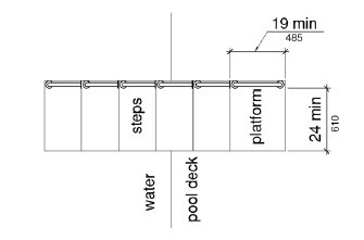
1009.5.2 Transfer Space. A transfer space of 60 inches (1525 mm) minimum by 60 inches (1525 mm) minimum with a slope not steeper than 1:48 shall be provided at the base of the transfer platform surface and shall be centered along a 24 inch (610 mm) minimum side of the transfer platform. The side of the transfer platform serving the transfer space shall be unobstructed.
|
|
|
Figure 1009.5.2 Clear Deck Space at Transfer Platform |
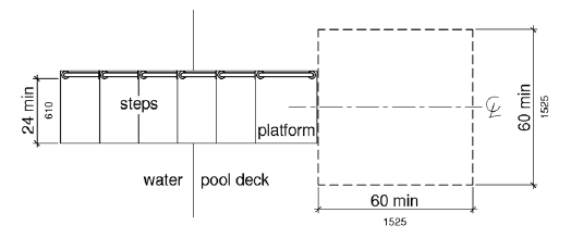
1009.5.3 Height. The height of the transfer platform shall comply with 1009.4.2.
1009.5.4 Transfer Steps. Transfer step height shall be 8 inches (205 mm) maximum. The surface of the bottom tread shall extend to a water depth of 18 inches (455 mm) minimum below the stationary water level.
|
|
|
Figure 1009.5.4 Transfer Steps |
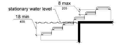
1009.5.5 Surface. The surface of the transfer system shall not be sharp and shall have rounded edges.
1009.5.6 Size. Each transfer step shall have a tread clear depth of 14 inches (355 mm) minimum and 17 inches (430 mm) maximum and shall have a tread clear width of 24 inches (610 mm) minimum.
|
|
|
Figure 1009.5.6 Size of Transfer Steps |
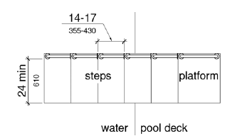
1009.5.7 Grab Bars. At least one grab bar on each transfer step and the transfer platform or a continuous grab bar serving each transfer step and the transfer platform shall be provided. Where a grab bar is provided on each step, the tops of gripping surfaces shall be 4 inches (100 mm) minimum and 6 inches (150 mm) maximum above each step and transfer platform. Where a continuous grab bar is provided, the top of the gripping surface shall be 4 inches (100 mm) minimum and 6 inches (150 mm) maximum above the step nosing and transfer platform. Grab bars shall comply with 609 and be located on at least one side of the transfer system. The grab bar located at the transfer platform shall not obstruct transfer.
EXCEPTION: Grab bars on transfer systems shall not be required to comply with 609.4.
|
|
|
Figure 1009.5.7 Grab Bars |
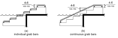
1009.6 Pool Stairs. Pool stairs shall comply with 1009.6.
1009.6.1 Pool Stairs. Pool stairs shall comply with 504.
EXCEPTION: Pool step riser heights shall not be required to be 4 inches (100 mm) high minimum and 7 inches (180 mm) high maximum provided that riser heights are uniform.
1009.6.2 Handrails. The width between handrails shall be 20 inches (510 mm) minimum and 24 inches (610 mm) maximum. Handrail extensions required by 505.10.3 shall not be required on pool stairs.
1010 Shooting Facilities with Firing Positions
1010.1 Turning Space. A circular turning space 60 inches (1525 mm) diameter minimum with slopes not steeper than 1:48 shall be provided at shooting facilities with firing positions.
1011 Outdoor Constructed Features
1011.1 General. All outdoor constructed features shall comply with 1011.2 and 1011.3. Outdoor constructed features specified in 1011.4 through 1011.8 shall comply with those provisions, as applicable.
1011.2 Clear Ground Space. A clear ground space complying with 1011.2 shall be provided at outdoor constructed features.
EXCEPTIONS:
1. Where individual outdoor constructed features are altered and the ground surface is not altered, the clear ground space shall not be required to comply with 1011.2.2 and 1011.2.3.
2. In alterations, when an entity determines that a condition in 1019 does not permit full compliance with a specific provision in 1011.2, the clear ground space shall comply with the provision to the extent practicable.
1011.2.1 Size and Location. The size and location of the clear ground space shall be in accordance with Table 1011.2.1. Unless otherwise specified in Table 1011.2.1, one full unobstructed side of the clear ground space shall adjoin or overlap an outdoor recreation access route or a trail, as applicable, or another clear ground space.
|
Table 1011.2.1 Clear Ground Space |
|
|
Outdoor Constructed Feature |
Minimum Size and Location |
|
Picnic tables |
36 inches (915 mm) on all usable sides of the table measured from the back edge of the benches |
|
Fire rings, grills, fireplaces, and woodstoves |
48 inches (1220 mm) by 48 inches (1220 mm) on all usable sides of the fire ring, grill, fireplace, and woodstove Center the space on each usable side of the grill, fireplace, and woodstove |
|
Trash and recycling receptacles |
36 inches (915 mm) by 48 inches (1220 mm) positioned for forward approach to the receptacle opening; or 30 inches (760 mm) by 60 inches (1525 mm) positioned for a parallel approach to the receptacle opening |
|
Water hydrants |
72 inches (1830 mm) by 48 inches (1220 mm) with the long side of the space adjoining or overlapping an outdoor recreation access route or trail, as applicable, or another clear ground space Locate the space so that the water spout is 11 inches (280 mm) minimum and 12 inches (305 mm) maximum from the rear center of the long side of the space |
|
Utility and sewage hookups |
30 inches (760 mm) by 60 inches (1525 mm) with the long side of the space adjoining or overlapping an accessible parking space or pull-up space for recreational vehicles Locate the space so that the hook-ups are at the rear center of the space Bollards or other barriers shall not obstruct the clear ground space in front of the hook-ups |
|
Outdoor rinsing showers |
60 inches (1525 mm) by 60 inches (1525 mm) centered on the shower heads Locate the space so that the shower pedestal or wall with the shower head are at the rear end of the space |
|
Benches |
36 inches (915 mm) by 48 inches (1220 mm) positioned near the bench with one side of the space adjoining an outdoor recreation access route or trail, as applicable The clear ground space shall not overlap the outdoor recreation access route or trail, or another clear ground space |
|
Viewing Scopes |
36 inches (915 mm) by 48 inches (1220 mm) positioned for forward approach to the viewing scope Provide knee and toe clearance complying with 306 under the viewing scope Locate the space so that the eyepiece is centered on the space |
1011.2.2 Surface. The surface of the clear ground space shall be firm and stable.
1011.2.3 Slope. The slope of the clear ground space surface shall not be steeper than 1:48 in any direction.
EXCEPTION: Where the surface is other than asphalt, concrete, or boards, slopes not steeper than 1:20 shall be permitted when necessary for drainage.
1011.2.4 Openings. Openings in the clear ground space surface shall not allow the passage of a sphere more than 1/2 inch (13 mm) in diameter.
1011.3 Operable Parts. Operable parts shall comply with 309.3 and 309.4.
EXCEPTIONS:
1. Fire rings, grills, fireplaces, wood stoves, water hydrants, and water utility hookups shall comply with 309.4 to the extent practicable.
2. Trash and recycling receptacles with hinged lids and controls to keep out large animals shall comply with 309.4 to the extent practicable.
3. Dumpster type trash and recycling receptacles shall not be required to comply with 309.3 and 309.4.
4. Sewage hatches shall not be required to comply with 309.3 and 309.4.
1011.4 Picnic Tables. Picnic tables shall comply with 1011.4.
1011.4.1 Height. The tops of picnic tables shall comply with 902.3.
1011.4.2 Wheelchair Space. Picnic tables shall provide at least one wheelchair space for each 24 linear feet (7320 mm) of usable table surface perimeter. Wheelchair spaces shall be 30 inches (760 mm) minimum by 48 inches (1220 mm) minimum. Wheelchair spaces shall be positioned for a forward approach to the table and provide knee and toe clearance complying with 306 under the table.
1011.5 Fire Rings, Grills, Fireplaces, and Wood Stoves. Fire rings, grills, fireplaces, and wood stoves shall comply with 1011.5.
1011.5.1 Fire Building Surfaces. Fire building surfaces shall be 9 inches (230 mm) minimum above the ground.
1011.5.2 Cooking Surfaces. Where provided, cooking surfaces shall be 15 inches (380 mm) minimum and 34 inches (865 mm) maximum above the ground.
1011.5.3 Raised Edges or Walls. Where fire rings, grills, or fireplaces are constructed with raised edges or walls, the depth of the raised edge or wall shall be 10 inches (255 mm) maximum.
1011.6 Water Spouts. Water spouts at water hydrants and water utility hook-ups shall be 28 inches (710 mm) minimum and 36 inches (915 mm) maximum above the ground.
1011.7 Outdoor Rinsing Showers. Outdoor rinsing showers shall provide at least one hand-held shower spray unit with a hose 59 inches (1500 mm) long minimum. The hand-held shower spray unit shall have at least one fixed position located 15 inches minimum (380 mm) and 48 inches (1220 mm) maximum above the ground.
EXCEPTION: Where vandalism is a consideration, a fixed shower head located at 48 in (1220 mm) above the ground shall be permitted in place of a hand-held shower spray unit.
1011.8 Viewing Scopes. Eyepieces on viewing scopes shall be 43 inches (1090 mm) minimum and 51 inches (1295 mm) maximum above the ground.
1012 Parking Spaces within Camping Units and Picnic Units and Pull-Up Spaces at Dump Stations
1012.1 General. Parking spaces within camping units and picnic units with mobility features and pull-up spaces for recreational vehicles at dump stations shall comply with 1012.
1012.2 Recreational Vehicles. Parking spaces and pull-up spaces for recreational vehicles shall be 20 feet (6100 mm) wide minimum.
EXCEPTION: Where two adjacent parking spaces are provided for recreational vehicles, one parking space shall be permitted to be 16 feet (4880 mm) wide minimum.
1012.3 Other Vehicles. Parking spaces for vehicles, other than recreational vehicles, shall be 16 feet (4880 mm) wide minimum.
EXCEPTION: Where two adjacent parking spaces are provided for vehicles, other than recreational vehicles, one parking space shall be permitted to be 8 feet (2440 mm) wide minimum.
1012.4 Surface. The surface of parking spaces and pull-up spaces shall be firm and stable.
1012.5 Slope. The slope of the surface of parking spaces and pull-up spaces shall not be steeper than 1:48 in any direction.
EXCEPTION: Where the surface is other than asphalt, concrete, or boards, slopes not steeper than 1:20 shall be permitted when necessary for drainage.
1012.6 Marking and signage. Ground marking and signage, if provided, shall comply with 502.1, 502.3.3 and 502.6.
1013 Tent Pads and Tent Platforms
1013.1 General. Tent pads and tent platforms shall comply with 1013.
EXCEPTION: When an entity determines that a condition in 1019 does not permit full compliance with a specific provision in 1013, the tent pad and tent platform shall comply with the provision to the extent practicable.
1013.2 Clear Ground Space. Clear ground space complying with 1013.2 shall be provided on all usable sides of tent pads and tent platforms.
1013.2.1 Size. The clear ground space shall be 48 inches (1220 mm) wide minimum.
1013.2.2 Surface. The surface of the clear ground space shall be firm and stable. The surface shall allow use of tent stakes and other tent securement devices.
1013.3 Slope. The slope of the surface of tent pads, tent platforms, and clear ground spaces shall not be steeper than 1:48 in any direction.
EXCEPTION: Where the surface is other than asphalt, concrete, or boards, slopes not steeper than 1:20 shall be permitted where necessary for drainage.
1013.4 Height. Tent platforms shall be 19 inches (485 mm) high maximum measured from the clear ground space to the tent platform surface.
1014.1 General. Camp shelters shall comply with 1014.
EXCEPTIONS:
1. When an entity determines that a condition in 1019 does not permit full compliance with a specific provision in 1014, the camp shelter shall comply with the provision to the extent practicable.
2. Camp shelters shall not be required to comply with 307.
1014.2 Entrance. Camp shelters shall provide an entrance complying with 1014.2.1 or 1014.2.2.
1014.2.1 Transfer Access. Where transfer access is provided at the entrance to a camp shelter, the entrance shall comply with 1014.2.1.
1014.2.1.1 Clear Ground Space. A clear ground space shall be provided at the entrance to the camp shelter. The clear ground space shall be 36 inches (915 mm) minimum by 48 inches (1220 mm) minimum and shall be positioned for a parallel approach to the camp shelter. One full unobstructed side of the clear ground space shall adjoin or overlap an outdoor recreation access route or trail, as applicable, or another clear ground space.
1014.2.1.1.1 Surface. The surface of the clear ground space shall be firm and stable.
1014.2.1.1.2 Slope. The slope of the surface of the clear ground space shall not be steeper than 1:48 in any direction.
EXCEPTION: Where the surface is other than asphalt, concrete, or boards, slopes not steeper than 1:20 shall be permitted where necessary for drainage.
1014.2.1.2 Floor Height. The camp shelter floor at the entrance shall be 19 inches (485 mm) high maximum measured from the clear ground space.
1014.2.2 Roll-in Access. Where roll-in access is provided at the entrance to a camp shelter, the entrance shall comply with 1014.2.2.
1014.2.2.1 Level or Sloped Entry Route. Camp shelters providing roll-in access shall have a level or sloped entry route complying 1016 or 1017, as applicable.
1014.2.2.2 Turning Space. A turning space complying with 304.3 shall be provided within the camp shelter.
1014.3 Floor. The floor within camp shelters shall comply with 1014.3.
1014.3.1 Surface. The floor surface shall be firm and stable.
1014.3.2 Slope. The slope of the floor surface shall not be steeper than 1:48 in any direction.
EXCEPTION: Where the floor surface is other than asphalt, concrete, or boards, slopes not steeper than 1:20 shall be permitted when necessary for drainage.
1015.1 General. Viewing areas shall comply with 1015.
EXCEPTION: In alterations, when an entity determines that a condition in 1019 does not permit full compliance with a specific provision in 1015, the viewing area shall comply with the provision to the extent practicable.
1015.2 Clear Ground Space. A clear ground space shall be provided at each distinct viewing location. The clear ground space shall be 36 inches (915 mm) minimum by 48 inches (1220 mm) minimum and shall be positioned for either a forward or parallel approach to the viewing location. One full unobstructed side of the clear ground space shall adjoin or overlap an outdoor recreation access route or trail, as applicable, or another clear ground space.
1015.3 Viewing Space. Each distinct viewing location shall provide a viewing space adjacent to the clear ground space required by 1015.2 through which the point of interest is viewable. The viewing space shall be 32 inches (815 mm) maximum and 51 inches (1295 mm) minimum high above the ground and shall extend the full width of the clear ground space.
EXCEPTION: Guards or similar safety barriers shall be permitted to obstruct the viewing space to the extent the obstruction is necessary for the guard or safety barrier to serve its intended purpose.
1015.4 Turning Space. A turning space complying with 304.3 shall be provided within viewing areas.
1015.5 Surface. The surface of clear ground spaces and turning spaces shall be firm and stable.
1015.6 Slope. The slope of the surface of clear ground spaces and turning spaces shall not be steeper than 1:48 in any direction.
EXCEPTION: Where the surface is other than asphalt, concrete, or boards, slopes not steeper than 1:20 shall be permitted when necessary for drainage.
1016 Outdoor Recreation Access Routes
1016.1 General. Outdoor recreation access routes shall comply with 1016.
EXCEPTIONS:
1. In alterations to existing camping facilities, picnic facilities, and trailheads, when an entity determines that a condition in 1019 does not permit full compliance with a specific provision in 1016 on a portion of an outdoor recreation access route, the portion of the outdoor recreation access route shall comply with the provision to the extent practicable.
2. At viewing areas, when an entity determines that a condition in 1019 does not permit full compliance on a portion of an outdoor recreation access route with a specific provision in 1016, the portion of the outdoor recreation access route shall comply with the provision to the extent practicable.
3. Where outdoor recreation access routes are provided within vehicular ways, outdoor recreation access routes shall not be required to comply with 1016.4, 1016.7, and 1016.8.
1016. 2 Surface. The surface of outdoor recreation access routes, passing spaces, and resting intervals shall be firm and stable.
1016.3 Clear Width. The clear width of outdoor recreation access routes shall be 36 inches (915 mm) minimum.
1016.4 Passing Spaces. Outdoor recreation access routes with a clear width less than 60 inches (1525 mm) shall provide passing spaces complying with 1016.4 at intervals of 200 feet (61 m) maximum. Passing spaces and resting intervals shall be permitted to overlap.
1016.4.1 Size. The passing space shall be either:
a. A space 60 inches (1525 mm) minimum by 60 inches (1525 mm) minimum; or
b. The intersection of two outdoor recreation access routes providing a T-shaped space complying with 304.3.2 where the base and the arms of the T-shaped space extend 48 inches (1220 mm) minimum beyond the intersection. Vertical alignment at the intersection of the outdoor recreation access routes that form the T-shaped space shall be nominally planar.
1016.5 Obstacles. Obstacles on outdoor recreation access routes, passing spaces, and resting intervals shall not exceed 1/2 inch (13 mm) in height measured vertically to the highest point.
EXCEPTION: Where the surface is other than asphalt, concrete, or boards, obstacles shall be permitted to not exceed 1 inch (25 mm) in height measured vertically to the highest point.
1016.6 Openings. Openings in the surface of outdoor recreation access routes shall not allow the passage of a sphere more than 1/2 inch (13 mm) in diameter.
1016.7 Slopes. The slopes of outdoor recreation access routes shall comply with 1016.7.
1016.7.1 Maximum Running Slope and Segment Length. The running slope of any segment of an outdoor recreation access route shall not be steeper than 1:10 (10%). Where the running slope of a segment of an outdoor recreation access route is steeper than 1:20 (5%), the maximum length of the segment shall be in accordance with Table 1016.7.1, and a resting interval complying with 1016.8 shall be provided at the top and bottom of each segment.
|
Table 1016.7.1 Maximum Running Slope and Segment Length |
||
|
Running Slope of Outdoor Recreation Access Route Segment |
Maximum Length of Segment |
|
|
Steeper than |
But not Steeper than |
|
|
1:20 (5%) |
1:12 (8.33%) |
50 feet (15 m) |
|
1:12 (8.33%) |
1:10 (10%) |
30 feet (9 m) |
1016.7.2 Cross Slope. The cross slope shall not be steeper than 1:48.
EXCEPTION: Where the surface is other than concrete, asphalt, or boards, cross slopes not steeper than 1:20 shall be permitted when necessary for drainage.
1016.8 Resting Intervals. Resting intervals shall comply with 1016.8.
1016.8.1 Length. The resting interval length shall be 60 inches (1525 mm) long minimum.
1016.8.2 Width. Where resting intervals are provided within an outdoor recreation access route, resting intervals shall be at least as wide as the widest segment of the outdoor recreation access route leading to the resting interval. Where resting intervals are provided adjacent to an outdoor recreation access route, the resting interval shall be 36 inches (915 mm) wide minimum.
1016.8.3 Slope. Resting intervals shall have slopes not steeper than 1:48 in any direction.
EXCEPTION: Where the surface is other than concrete, asphalt, or boards, slopes not steeper than 1:20 shall be permitted when necessary for drainage.
1016.8.4 Turning Space.
Where resting intervals are provided adjacent to an outdoor recreation access
route, a turning space complying with 304.3.2 shall be provided.
Vertical alignment between the outdoor recreation access route, turning space,
and resting interval shall be nominally planar.
1016.9 Protruding Objects. Constructed elements on outdoor recreation access routes, passing spaces, and resting intervals shall comply with 307.
1017.1 General. Trails shall comply with 1017.
EXCEPTIONS:
1. When an entity determines that a condition in 1019 does not permit full compliance with a specific provision in 1017 on a portion of a trail, the portion of the trail shall comply with the provision to the extent practicable.
2. After applying Exception 1, when an entity determines that it is impracticable for the entire trail to comply with 1017, the trail shall not be required to comply with 1017.
1017.2 Surface. The surface of trails, passing spaces, and resting intervals shall be firm and stable.
1017.3 Clear Tread Width. The clear tread width of trails shall be 36 inches (915 mm) minimum.
1017.4 Passing Spaces. Trails with a clear tread width less than 60 inches (1525 mm) shall provide passing spaces complying with 1017.4 at intervals of 1000 feet (300 m) maximum. Where the full length of a trail does not fully comply with 1017, a passing space shall be located at the end of the trail segment that fully complies with 1017. Passing spaces and resting intervals shall be permitted to overlap.
1017.4.1 Size. The passing space shall be either:
a. A space 60 inches (1525 mm) minimum by 60 inches (1525 mm) minimum; or
b. The intersection of two trails providing a T-shaped space complying with 304.3.2 where the base and the arms of the T-shaped space extend 48 inches (1220 mm) minimum beyond the intersection. Vertical alignment at the intersection of the trails that form the T-shaped space shall be nominally planar.
1017.5 Tread Obstacles. Tread obstacles on trails, passing spaces, and resting intervals shall not exceed 1/2 inch (13 mm) in height measured vertically to the highest point.
EXCEPTION: Where the surface is other than asphalt, concrete, or boards, tread obstacles shall be permitted to not exceed 2 inches (50 mm) in height measured vertically to the highest point.
1017.6 Openings. Openings in the surface of trails, passing spaces, and resting intervals shall not allow the passage of a sphere more than 1/2 inch (13 mm) in diameter.
1017.7 Slopes. The slopes of trails shall comply with 1017.7.
1017.7.1 Maximum Running Slope and Segment Length. Not more than 30 percent of the total length of a trail shall have a running slope steeper than 1:12 (8.33%). The running slope of any segment of a trail shall not be steeper than 1:8 (12%). Where the running slope of a segment of a trail is steeper than 1:20 (5%), the maximum length of the segment shall be in accordance with Table 1017.7.1, and a resting interval complying with 1017.8 shall be provided at the top and bottom of each segment.
|
Table 1017.7.1 Maximum Running Slope and Segment Length |
||
|
Running Slope of Trail Segment |
Maximum Length of Segment |
|
|
Steeper than |
But not Steeper than |
|
|
1:20 (5%) |
1:12 (8.33%) |
200 feet (61 m) |
|
1:12 (8.33%) |
1:10 (10%) |
30 feet (9 m) |
|
1:10 (10%) |
1:8 (12%) |
10 feet (3050 mm) |
1017.7.2 Cross Slope. The cross slope shall be not be steeper than 1:48.
EXCEPTION: Where the surface is other than concrete, asphalt, or boards, cross slopes not steeper than 1:20 shall be permitted when necessary for drainage.
1017.8 Resting Intervals. Resting intervals shall comply with 1017.8.
1017.8.1 Length. The resting interval length shall be 60 inches (1525 mm) long minimum.
1017.8.2 Width. Where resting intervals are provided within the trail tread, resting intervals shall be at least as wide as the widest segment of the trail tread leading to the resting interval. Where resting intervals are provided adjacent to the trail tread, the resting interval clear width shall be 36 inches (915 mm) minimum.
1017.8.3 Slope. Resting intervals shall have slopes not steeper than 1:48 in any direction.
EXCEPTION: Where the surface is other than concrete, asphalt, or boards, cross slopes not steeper than 1:20 shall be permitted when necessary for drainage.
1017.8.4 Turning Space. Where resting intervals are provided adjacent to the trail tread, a turning space complying with 304.3.2 shall be provided. Vertical alignment between the trail tread, turning space, and resting interval shall be nominally planar.
1017.9 Protruding Objects. Constructed elements on trails, passing spaces, and resting intervals shall comply with 307.
1017.10 Trailhead Signs. Trail information signs at trailheads shall include the following:
1. Length of the trail or trail segment;
2. Surface type;
3. Typical and minimum tread width;
4. Typical and maximum running slope; and
5. Typical and maximum cross slope.
1018.1 General. Beach access routes shall comply with 1018.
EXCEPTIONS:
1. When an entity determines that a condition in 1019 does not permit full compliance with a specific provision in 1018 on a portion of a beach access route, the portion of the beach access route shall comply with the provision to the extent practicable.
2. After applying Exception 1, when an entity determines that it is impracticable to provide a beach access route complying with 1018, a beach access route shall not be required.
3. Removable beach access routes shall not be required to comply with 1018.7, 1018.8, and 1018.10.
1018.2 Connections. Beach access routes shall connect an entry point to the beach to the:
1. High tide level at tidal beaches;
2. Mean high water level at river beaches; or
3. Normal recreation water level at lake, pond, and reservoir beaches.
1018.3 Surface. The surface of beach access routes and resting intervals shall be firm and stable.
1018.4 Clear Width. The clear width of beach access routes shall be 60 inches (1525 mm) minimum.
EXCEPTION: At dune crossings, the clear width of beach access routes that are not removable shall be permitted to be reduced to 48 inches (1220 mm) minimum.
1018.5 Obstacles. Obstacles on beach access routes and resting intervals shall not exceed 1/2 inch (13 mm) in height measured vertically to the highest point.
EXCEPTION: Where the surface is other than asphalt, concrete, or boards, obstacles shall be permitted to not exceed 1 inch (25 mm) in height measured vertically to the highest point.
1018.6 Openings. Openings in the surface of beach access routes and resting intervals shall not allow the passage of a sphere more than 1/2 inch (13 mm) in diameter.
1018.7 Slopes. The slopes of beach access routes shall comply with 1018.7.
1018.7.1 Maximum Running Slope and Segment Length. The running slope of any segment of a beach access route shall not be steeper than 1:10 (10%). Where the running slope of a segment of a beach access route is steeper than 1:20 (5%), the maximum length of the segment shall be in accordance with Table 1018.7.1, and a resting interval complying with 1018.8 shall be provided at the top and bottom of each segment.
|
Table 1018.7.1 Maximum Running Slope and Segment Length |
||
|
Running Slope of Beach Access Route Segment |
Maximum Length of Segment |
|
|
Steeper than |
But not Steeper than |
|
|
1:20 (5%) |
1:12 (8.33%) |
50 feet (15 m) |
|
1:12 (8.33%) |
1:10 (10%) |
30 feet (9 m) |
1018.7.2 Cross Slope. The cross slope shall not be steeper than 1:48.
EXCEPTION: Where the surface is other than concrete, asphalt, or boards, cross slopes not steeper than 1:20 shall be permitted when necessary for drainage.
1018.8 Resting Intervals. Resting intervals shall comply with 1018.8.
1018.8.1 Size. Resting intervals shall be 60 inches minimum (1525 mm) by 60 inches (1525 mm) minimum.
1018.8.2 Slope. Resting intervals shall have a slope not steeper than 1:48 in any direction.
EXCEPTION: Where the surface is other than concrete, asphalt, or boards, cross slopes not steeper than 1:20 shall be permitted when necessary for drainage.
1018.9 Protruding Objects. Constructed elements on beach access routes and resting intervals shall comply with 307.
1018.10 Dune Crossings. Where the slope of a beach access route at a dune crossing is steeper than 1:20 (5%), handrails complying with 505 and curbs or barriers shall be provided. The curbs or barriers shall prevent the passage of a 2 inch (50 mm) diameter sphere, where any portion of the sphere is within 2 inches (50 mm) of the crossing surface.
1019 Conditions for Exceptions
1019.1 General. Exceptions to specific provisions in 1011, 1013, 1014, 1015, 1016, 1017, and 1018 shall be permitted when an entity determines that any of the following conditions does not permit full compliance with the provision:
1. Compliance is not practicable due to terrain.
2. Compliance cannot be accomplished with the prevailing construction practices.
3. Compliance would fundamentally alter the function or purpose of the facility or the setting.
4. Compliance is limited or precluded by any of the following laws, or by decisions or opinions issued or agreements executed pursuant to any of the following laws:
• Endangered Species Act (16 USC 1531 et seq.);
• National Environmental Policy Act (42 USC 4321 et seq.);
• National Historic Preservation Act (16 USC 470 et seq.);
• Wilderness Act (16 USC 1131 et seq.); or
• Other federal, state, or local law the purpose of which is to preserve threatened or endangered species; the environment; or archaeological, cultural, historical, or other significant natural features.